Tutorials
These tutorials are for information purposes only and if performed should be done with caution.
JNX is not responsible for any damage to person or property.
-Xian Xi
To view the available tutorials and guides, please use the navigation panel on the left. Clicking a main section will show you the available categories for browsing. Choosing a category will then display all available items within that category.
Welcome to NeogeoMods.com, part of Jamma-Nation-X. Please use the menu to the left to explore our collection of Neo related tutorials as well as various other systems and projects. You can use the navigation at the top of your screen to visit the other sections of JNX.
Also be sure to stop by the JNX store and check out all the great deals on your Neo and arcade needs.
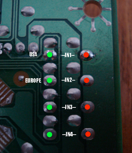
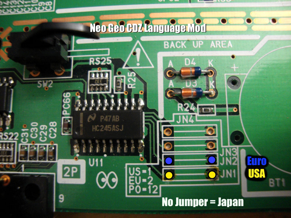
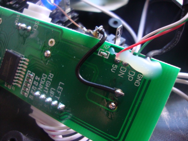
In the above picture is the underside of the controller board in the Neo Geo CD. As you can see in the above picture, you simply just need to set a jumper from the red dot to the corresponding green dot. JN1 is for USA, JN2 is for Euro and no jumpers set is Japan..

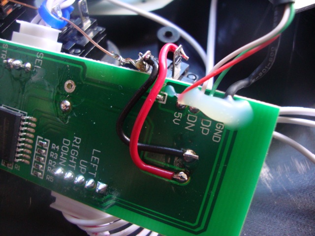
In the above picture is a simple way to add a region switch. You will need a SPDT switch which means Single Pole-Double Throw aka ON-OFF-ON. Since the common factor in the jumer settings is the ground we will set that to the center pin of the switch. Connect the point from JN1 to the top pin on the switch and the point on JN2 to the bottom one. This way Your switch will change the language as you want it to. Your switch will be USA (top)-Japan (middle)-Euro (bottom). And that's it, you're done. Now go have some red blood via the japanese setting.
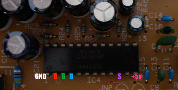
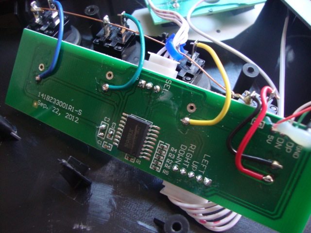
In the above picture is the points on the internal encoder to pull the Red, Green, Blue and Sync signals from. So if you ever plan on adding component output to your Neo Geo CD, all the points you need are right there.
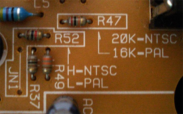
If you have a PAL NGCD and want to change it to NTSC: Remove jumper JN1, Change resistor R47 to 20k 1/4 watt, Add Resistor R52 1K 1/4 watt.
If you have an NTSC NGCD and want to change it to PAL: Add jumper JN1, Change R47 to 16k 1/4 watt, Remove resistor R52. In some cases you may need to replace the colorburt crystal to a PAL compatible one.
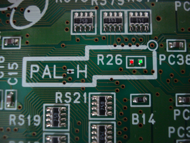
To change your Neo Geo CD to a 50hz display, short the connection of R26(Connect the red dot to the green dot). If your Neo CD is currently 50hz and want to change it to 60hz, do the opposite and remove the connection. You can also add a switch using a SPST (ON-ON) and just wire 2 pins using the 2 points in the picture (Red point to 1 the middle leg of the switch and Green point another leg on the switch). This way you can switch it between 50hz and 60hz.

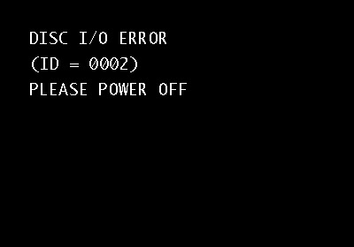
The Neo Geo CD has a few error codes that it spits out from time to time.
Here are a few:
0000 - General Error. Clear disc of any dust or debris.
0001 - Disc Read Error. Usually due to a dirty/damaged laser lens or disc.
0002 or 0003 - Mechanical Problem with Unit or possibly a copy protection alert.
A lot of the errors from the system are caused by general overheating, dirty lens or a burnt disc made with a crappy quality CD. If you have the unit on a carpet, pick it up and place on a shelf or other flat hard surface. If the errors continue after cleaning the disc and lens and changing unit locations then seek assistance. One thing it could be is a failing laser and it may need to be adjusted.
This is what the error screen will look like when you get it.
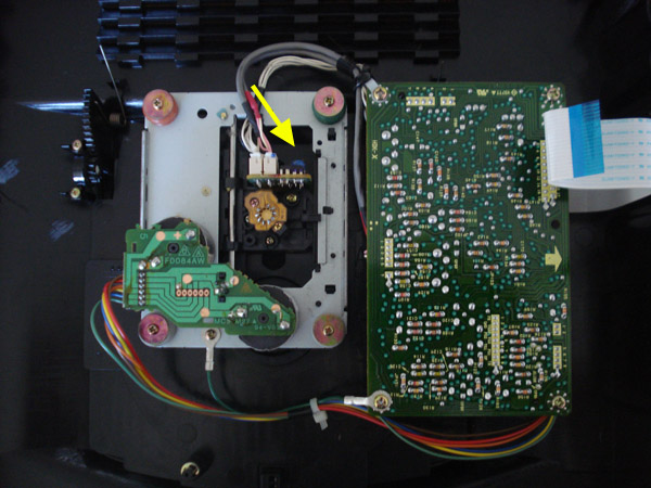
Do you get an error message all the time on your NGCD even though you clean and clean to no avail? There is a good chance that your laser could be failing. Since locating new replacement parts is rather immpossible for the NGCD the only thing you can really do is adjust the strength of the laser.
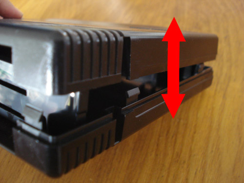
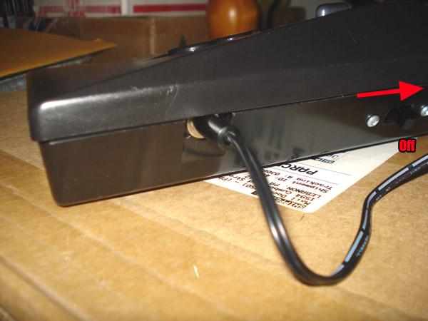
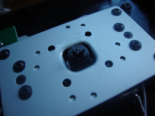
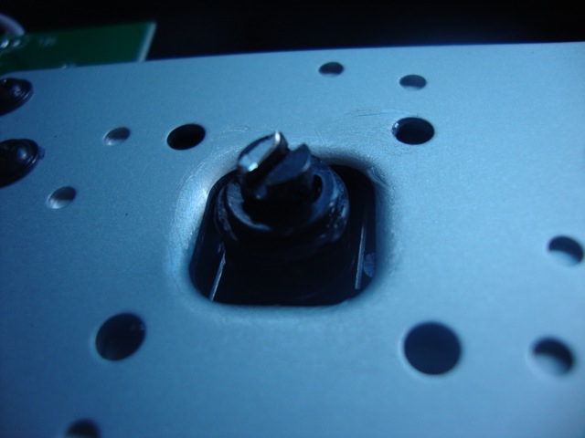
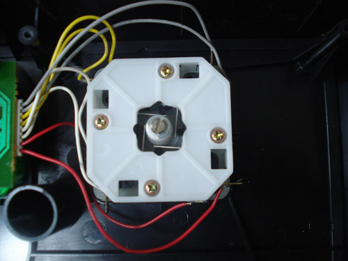
First open your NGCD console up and set the top half on the side. The arrow marks where the laser pot is that needs adjusting.
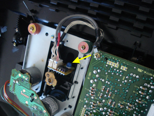
We will be adjusting the pot by turning it clockwise to increase laser power. You will need a flat head screwdriver or you can turn it by hand.
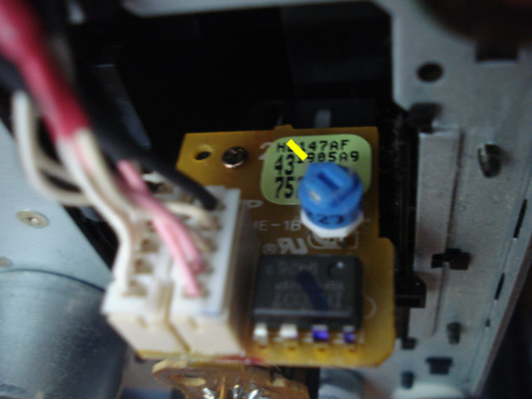
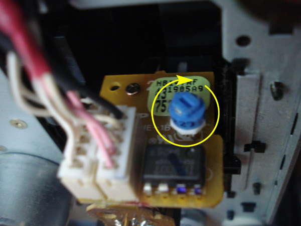
One very important thing to do is to mark where the pot originally was incase you have retard strength and can't control yourself while turning the pot.
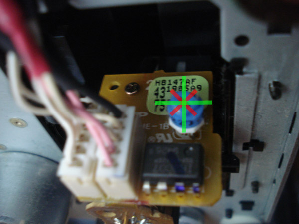
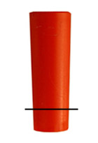
One other very important thing to remember is to only turn in 1/8th turn increments at a time. As much as you want to put it to full blast you need to remember you will kill it faster that way, you are only making a small adjustment. In the picture above is the pot broken down into 8 sections so you can see how much you can turn it at a time. Take your time while turning the pot.
After you turn the pot 1/8th of a turn go ahead and test the unit to see if the system now reads the discs, if it doesn't then try adjusting it another 1/8th turn. Keep trying until it works. If you have already adjusted the pot 1/2 turn and you still get errors your laser is most likely dead. You will need to find a replacement.
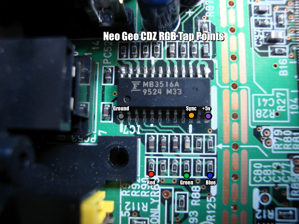
Here are the locations to tap RGB from when adding an internal component encoder.
The left side of the jumpers is where the actual signal is, the right side is just ground. No jumpers set is Japan region, JN1 is USA and JN2 is Euro. If you are making a language switch, you can use a SPDT(Single pole-double throw aka ON-OFF-ON) switch. Just wire ground to the center pin and the outer pins to the two jumpers on the left side.
The above picture is the underside of your AES motherboard at the headphone jack location.
In the above picture is 4 places where you can get stereo sound from. Now before opening your AES to do this remember that you can buy a 1/8" stereo to dual RCA phono cord and just plug it in to the headphone jack.
If you are planning on adding stereo jacks to the back of your AES as well as video then keep reading.
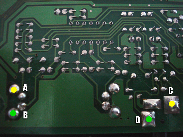
In the picture you see 4 dots 2 green and 2 yellow. On the left side you see dots A and B, these 2 points are a constant line level volume dots C and D are adjustable in volume via the heaphone volume slider. Choose which ever set you want to use, just remember the dots above go to the center pin on the RCA jack and ground goes to the outer ring of the jack..
A and C are Left Audio
B and D are Right Audio
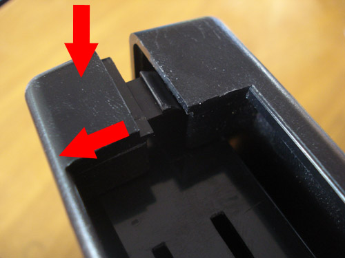
The above picture is the first tab you need to pop open on the cart near the slot. Simply push the front edge of the cart (Label facing you) down then pull towards you. Do NOT pull using the cart slot area as you will create stress marks on the plastic.
It is easiest when you have your thumb on the down arrow spot and then have your middle finger on the opposite side of the cart and pull down then out.
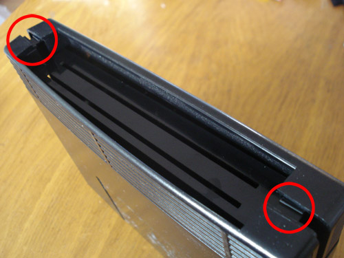
There are 2 of these tabs, one on each side. Pop both open.
Once you pop the 2 tabs by the slot there are 2 more along each side of the cart.
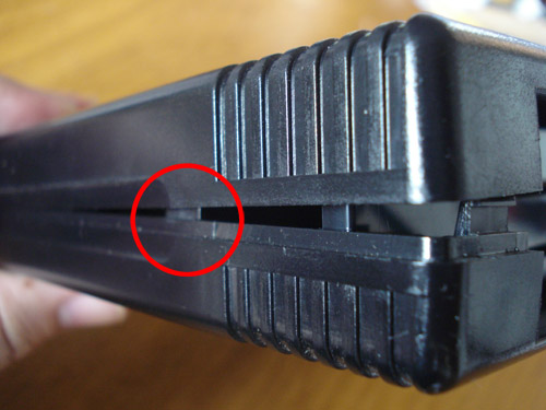
Gently pry the cart open on both sides.
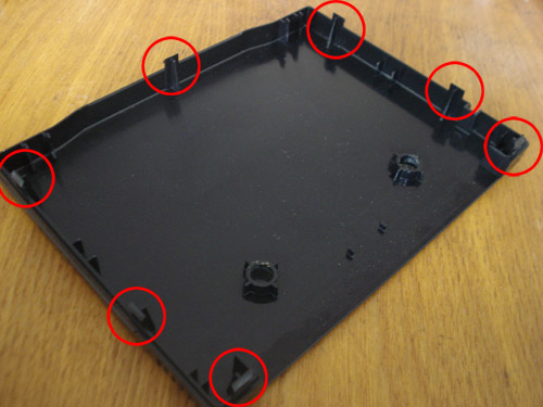
These are all the tabs located in the cart.
This is your AES reset button, also the same as an Old Style stick button. Remove the 2 tabs. I use a Dremel as it's easiest.
Once the tabs are removed you should have something like this.
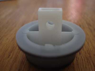
Now drill a 1/8" hole in this approximate location.
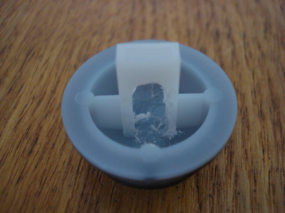
Using your Dremel, grind out the center rib to bottom of the button and a little bit of the sides that touch the bottom of the button. Do not grind too deep into the button. Try to grind only as deep as the surrounding areas.
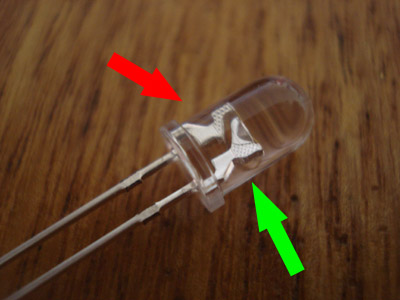
This is a 5mm LED. The left side with the red arrow is the positive side also known as the anode and the right side with the green arrow is the negative also known as the cathode.
You will need to know your LEDs forward voltage reading. Usually light colors such as white, blue and green have a forward voltage of 3.2v. Since we will be tapping the power source from the AES, it will be a +5v source so you will need a 100 ohm resistor.
To disperse the light evenly in the reset button I usually sand the top down on the LED almost all the way down. Doing so lets the light spread and not be as focused.
You might have seen some mods where the LED in the button is very evident as the center of the button is the brightest part of it. What I also like to do is use a black sharpie and black off the top of the LED that was just shaved off to kill the light focus even more, if you have a better black paint that's even better.
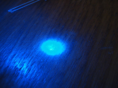
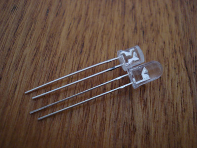
Here you can see how focused the light is before I sanded the top off. Notice how far away the LED is from the table and I still have a very focused light.
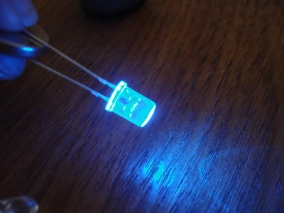
Here the LED is after I sanded it down, notice how the light isn't as focused in one spot.
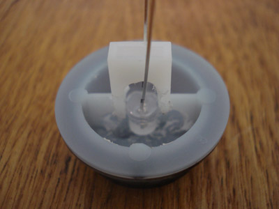
Now insert your LED into the button like so. At this pint you might want to mark down which side is positive and negative. I usually put a black mark on the leg of the cathode.
To help distribute the light better I like to fill the voids with hot glue. This is just the way I do it. You can leave it out if you want. If you do decide to use hot glue just remember to spread it evenly in the button.
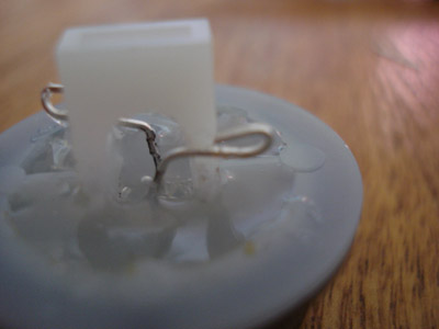
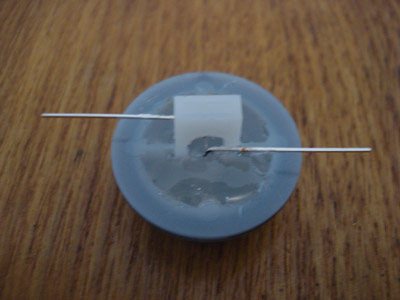
After the glue has hardened I cut the legs and create eyes(hooks) to prepare for soldering.
For a power LED I use 28awg wire. Go ahead and solder the wires to the button. Keep track of the negative.
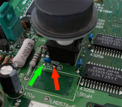
In your AES close to the reset button are a bunch of caps you can use for your power source, here is an example. Remember you will need to solder the 100 ohm resistor to the negative wire and connect it to the left leg of the cap where the GREEN arrow is. And of course red is for the positive side.
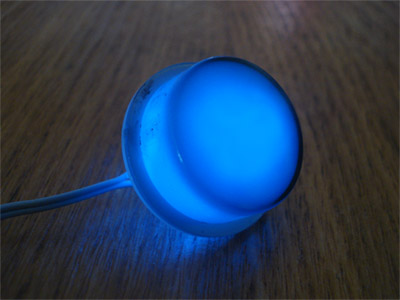
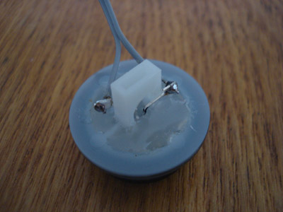
This is what the LED looks like with the light spread evenly in the button.
Overclocking your Neo Geo AES console, info by 68K.
To overclock your AES you will need a few things:
1 - 4 Pin Oscillator Crystal (I'm using a 15mhz)
1 - Chassis Mount Single Pole Single Throw Toggle switch
1 - Small Piece of Perfboard(To mount the oscillator to unless you prefer to have it dangle)
Some wire (I am using 28awg)
Solder
Soldering Iron
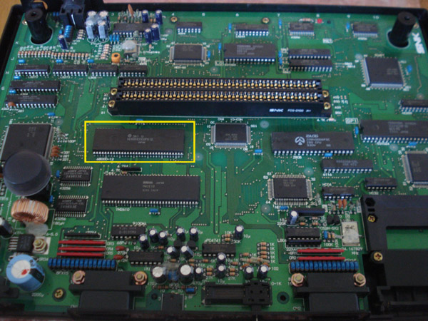
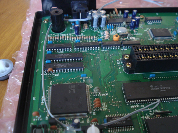
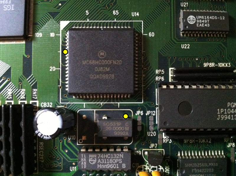
First you will need to locate your CPU. In the above picture is a second generation AES, note the CPU location. If you have a first generation AES the CPU will be right above the cart slot in the middle.
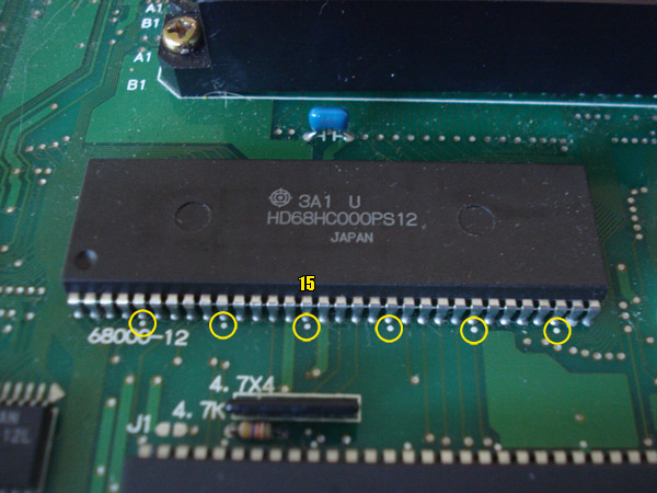
In this picture is the CPU, the circled dots are board markings which are counted every 5 pins on the CPU. We will be working with Pin 15.
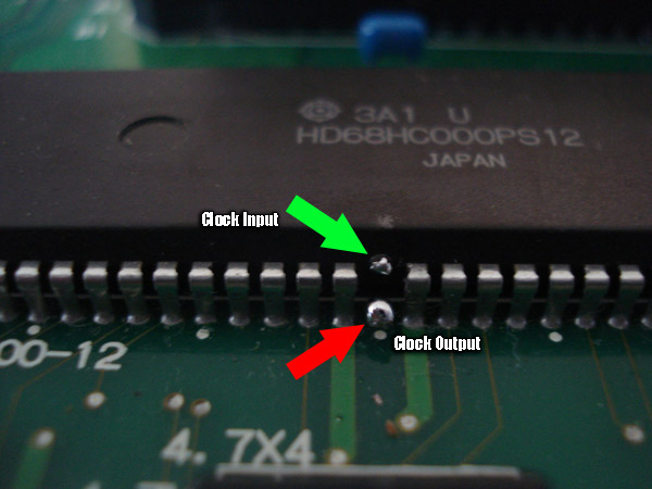
This is the hardest part of the tutorial, cutting the clock input pin. From my experience it is easiest to do this mod by cutting the pin in the middle and then gently bending both ends away from each other creating a gap. Go ahead and add a little solder to both leads.
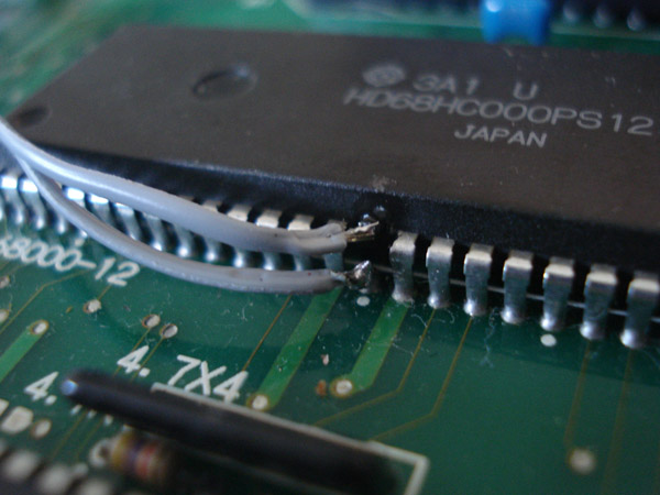
Now connect 2 wires to the CPU, one to the upper pin and one to the lower pin. Keep note which wire is connected to the actual chip as this is the clock input pin. The other is the stock clock signal output.
**Note: In some cases the pulse from both crystals merge on the signal input wire since they are next to each other. In this case it is best to run the stock signal wire UNDER the AES board instead of the top.
After I connect the 2 wires to the CPU I like to route them around the cart slot as seen above. I use a little hot glue to keep the wires from shifting.
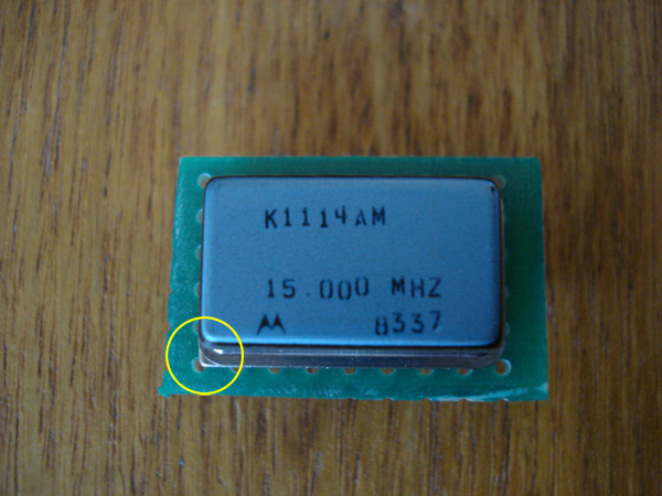
This is the osciallator crystal. My local parts store only had 15mhz and above. Keep in mind that the stock speed is 12mhz and you want to keep the mod within reason. You want to keep it within 35% of the stock speed, in this case a max of 16mhz. Keep in mind the higher you go you are more likely to encounter problems on certain games while others play fine. Most common speed to use is 14mhz. Notice the yellow circle. Most crystals have a black dot in one corner to tell you the orientation of the pinout. This crystal is a bit different and instead has one sharp corner and 3 round ones.
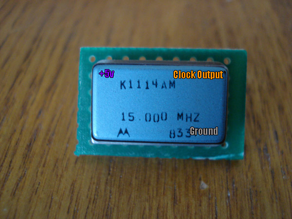
The above pinout relates to the pins directly under them. You will only be using 3 of the 4 pins.
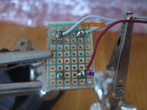
A pic of the solder side of the board. Make sure you leave enough wire for where you want to mount your crystal. Here I am using a tool called "Helping Hands", great tool to have handy (No pun intended).
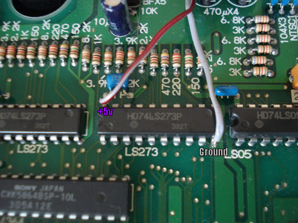
The crystal will need to be supplied with +5v as well as ground. I tap these from the above LS273. Ground is on pin 12 and +5v on pin 24.
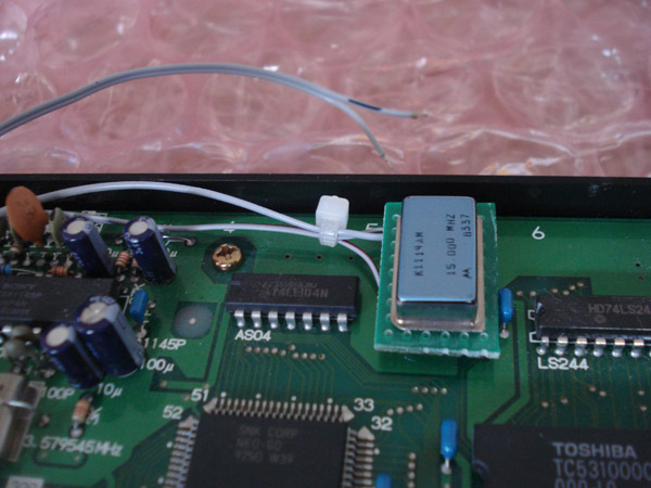
I chose to mount my small board in this spot, section A5 on the motherboard which is to the right of the Sony video encoder. I used hot glue as a foundation first and let it semi-harden then glued the board to it.
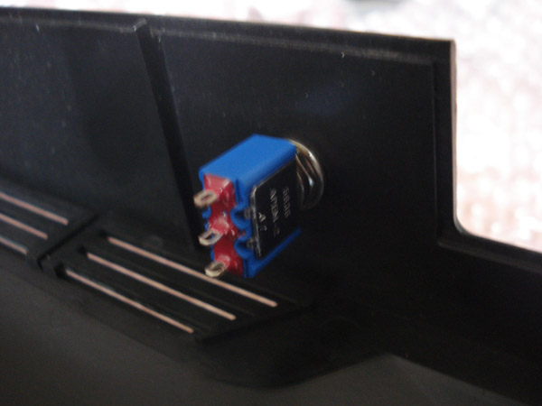
For the switch I opted to use a SPST (ON-ON) chassis/panel mount toggle switch as it was readily available to me. You can also use a slide switch if you prefer.
This is the view of the other side of the switch.
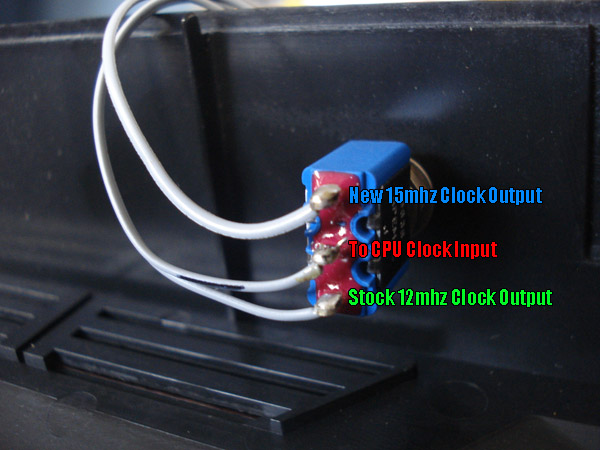
When wiring your switch keep note of the orientation of your signals. If you follow the pinout above, your switch will function the correct way, UP for ON and DOWN for OFF. If you switch the top and bottom wire the switch will be opposite. The top pin comes from the new crystal output, the middle pin is the clock input pin (top half) and the bottom pin connects to the stock clock output (bottom half).
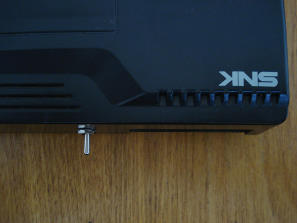
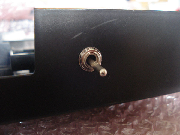
Now put your AES back together and try it out. Make sure you only touch the switch when the power is off. If you switch while the power is on the system will reboot.
Click here (or Save As) to see the console at 12mhz.
Click here (or Save As) to see the console at 15mhz.
Both videos captured via Composite video output. In the videos you can see that the breakable items cause slowdown and flicker at stock speed. At the new 15mhz speed the breakable items do not flicker or cause any slowdown.
Keep in mind that some games may display graphical glitches during gameplay. Some of the newer games are optimized for best performance on the Neo. These games are usually 1999 and newer releases. For example Metal Slug 2 even at 16mhz will run slow but Metal Slug X (which is already fast) at 16mhz doesn't look any faster since it's optimized.
**Important Note: If you get a clicking screen while trying the overclock setting it means the 2 signal wires are too close (Stock and New Speed) together and the pulses are crossing so the CPU doesn't know what speed to run at. Just separate the 2 wires.
In this tutorial you will learn how to turn a regular old style stick into a wireless controller.
Parts Needed:
1 Tototek PS2 to Neo Controller Adapter
1 Neo Geo Old Style Stick with Sanwa or Seimitsu Buttons
1 2 AA Battery Holder with Leads
1 Pelican Brand PS2 2.4ghz Wireless Controller with Receiver
1 SPST (ON-OFF) Slide Switch or Toggle Switch - Panel Mount
2 2.5mm Barrell Jack - Panel Mount
2 2.5mm Barrell Jack Tips
1 AA Battery Charger
2 AA Rechargeable Batteries, I use 2700mAh batteries
Hot Glue
First thing you need to do is open the Pelican wireless controller. There are phillips screws.
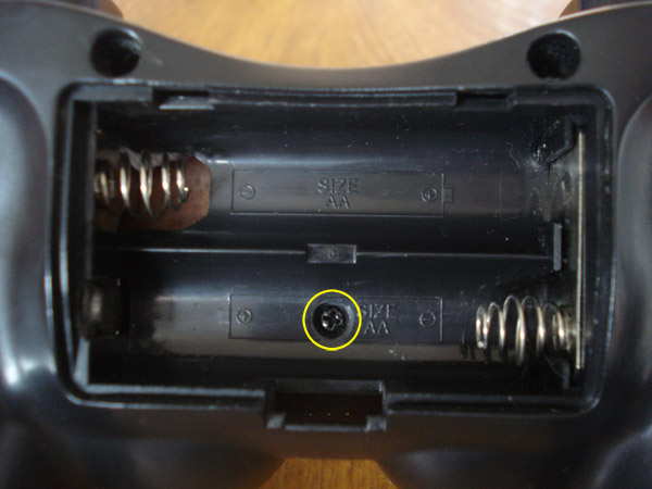
There is one screw in the battery compartment as well.
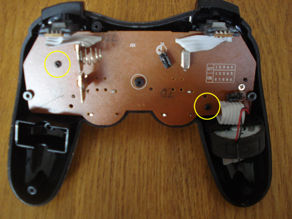
Once you get the controller open go ahead and remove these 2 screws. You can also remove the battery spring and terminals you see above as well as the 2 trigger buttons used for L1, L2, R1 and R2 as they are not needed UNLESS you want to use them to activate the turbo feature of the Tototek converter.
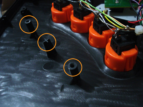
When you open your Neo stick you will need to cut these 3 posts flat. This is where the PS2 wireless control board will sit. After you cut the posts you can then apply some hot glue in the 3 spots they were in and lay your control board there to secure it.
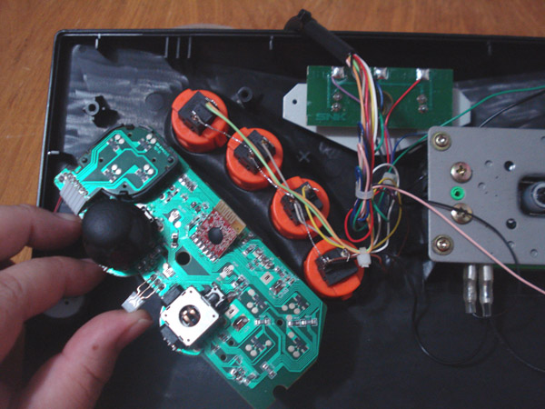
Here is the placement of the control board. When I installed mine I removed the 2 analog sticks on the control board since I wouldn't be using them. You of course have to desolder them from the board to remove them. If you prefer to leave them on just flip the board around to where the thumbsticks are by the buttons instead.
These are the wires you will be using to solder to the control board for the directional functions. On the control board Up has it's own ground and the other 3 directions share a ground so you will need to follow suit on the 4 microswitches as well which means all 4 microswitches on the joystick can not use the same ground.
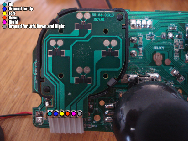
Now you can go ahead and start soldering. One weird thing about these controllers is that for the directional buttons you need to solder to the solder joints in the picture. If you solder directly to the pads it won't work. Remember that Up has it's own ground and this is due to the logic of the controller.
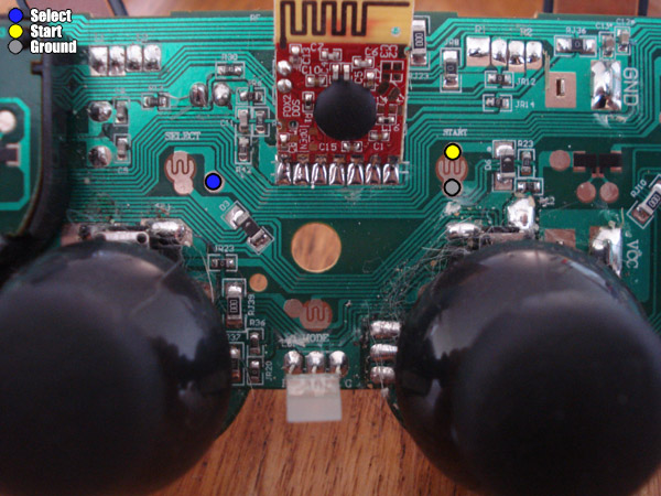
These are the solder points for the Select and Start buttons which also use their own ground.
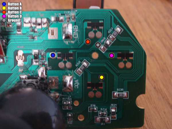
These are the solder points for the buttons. They all use 1 common ground.
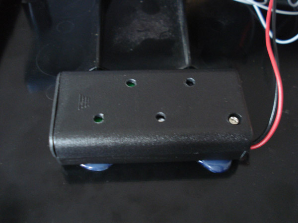
This is where I mounted the battery pack which is just a simple 2 AA battery pack you can get from your local supply store. I drilled a few holes just to let some heat out in case they get hot during charging. I put a few dabs of hot glue to hold it in place. The distance from the 2 fins for the stick is about 3/4". Anything closer and you might have to bend some terminals on the microswitches for the stick. Positive(Red Lead) goes to the slide switch and Negative(Black Lead) goes to the ground solder pad on the control board.
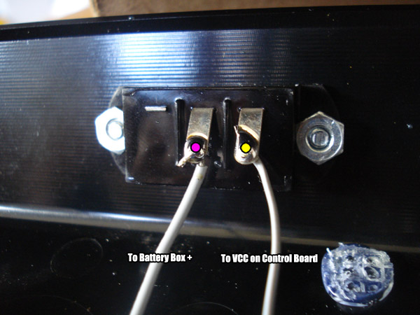
This is a panel mount SPST slide switch. You can mount it where you want I just chose the back panel. One pin goes to the battery pack positive (Red lead) and the other pin goes to the VCC solder pad on the control board.
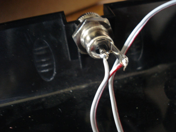
This is the 2.5mm barrell jack. Center pin is positive and outer is negative. Of course the Positive is connected to the red lead on the battery pack and the negative is connected to the black lead.
I used a Fuji brand battery charger that I have had for a while. Most battery chargers charge batteries in a series, this is why most charger require you to charge a minumum of 2 batteries at a time. Just open up your battery charger and look at the contacts, you should see one connected to one of the positives and another connecting to the negative of the 2nd battery. Wire the positive to the center pin of the 2.5mm barrell jack and the negative to the outside tab. After soldering the jack you will need to make a male-male cable to connect the charger to your stick. You can do so by picking up 2 2.5mm jack tips and use some 22-26 gauge wire. Make sure you don't cross the connections so that the center pin on one side is also the center pin on the other.
One very important thing, when you are charging your wireless stick turn your slide switch to the OFF position first!!!
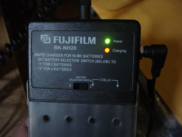
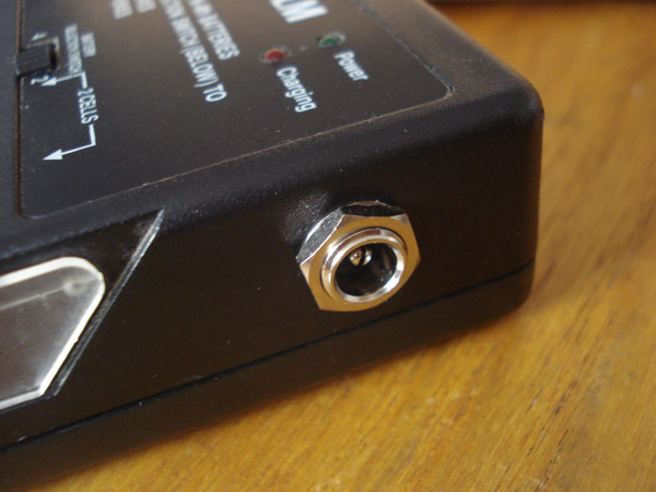
Plug in the cord you made to the back of the stick and then into the jack you made on the charger and you should see something like this.
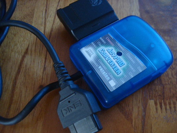
This is the Tototek PS2 to Neo converter with the 2.4ghz receiver plugged into it. Just plug it into your Neo to complete the wireless fun.
That's pretty much the jist of the mod, if you want to be a total bad ass you can install the tototek converter with the PS2 receiver internally in the AES for a completetly hidden look. If you have any questions please feel free to contact me.
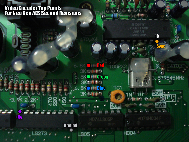
The above picture is the encoder area of your second revision AES motherboard. If your's does not look like this then you have a first revision motherboard.
The tap points are clearly marked in the picture and are the optimal points to get signals from.
Red, Green and Blue are grabbed from the LEFT side of the 6.8K resistors. Sync is on pin 10 of the Sony encoder,
it is a tight fit and you may have to slightly bend the capacitor in front of it.
+5v and ground can be tapped from the LS273 in the picture. Ground is on pin 10 and +5v is on pin 20.
If your picture is too bright, you might need to add some resistor between the RGB source and the encoder's RGB input. Usually 100-125ohm 1/4 watt resistors do the trick.
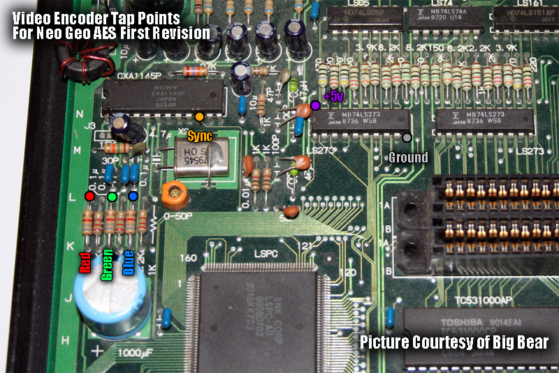 The above picture is the encoder area of your first revision AES motherboard. If your's does not look like this then you have a second revision motherboard.
The tap points are clearly marked in the picture and are the optimal points to get signals from. Red, Green and Blue are grabbed from the RIGHT side of the 6.8K resistors as seen in the pic. Sync is on pin 10 of the Sony encoder. +5v and ground can be tapped from the LS273 in the picture. Ground is on pin 10 and +5v is on pin 20.
Info Courtesy of MKL. Mod by RockstarRunner.
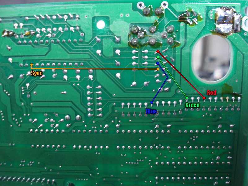
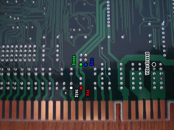
The above picture is the back of the AES board right behind the encoder. The above points are the optimum signal points. Simply make the connection using an 82ohm 1/4 watt resistor on the Red, Green and Blue lines. The Sync line doesn't need the resistor.
According to MKL the resistor is need since the pure RGB signals are too bright to display properly on a TV.
**Note: The bottom plastic shell has an indented vent near the point where you're doing the mod so make sure you're soldering the wires in such a way that you can fit the board back into the shell.
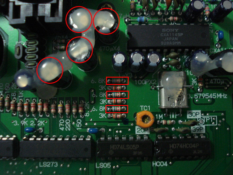
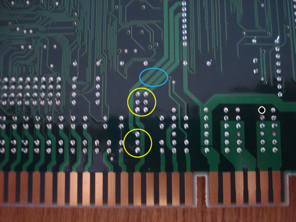
The above picture is of the encoder section of the board. You will need to remove the 4 circled capacitors and the 3 marked resistors.
Due to new info, you do not need to remove the (3) 6.8k resistors for the mod to work.
**Note: After having done this mod, your Neo-Geo will no longer display composite out video from the onboard encoder! Only RGB.
After having done this mod, the vertical lines that where present accross the screen are now gone, the colours are vibrant, and the image is sharp and clear.
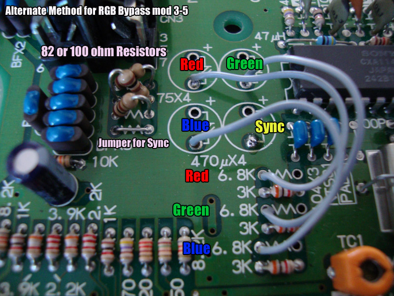
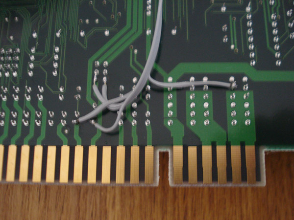
Here is an Alternate method I did on a 3-5, this is mod was by customer request.
If you'd like to keep composite video you can leave the 6.8k resistors, 4th cap for composite (says sync in pic) and leave the 75ohm resistor instead of putting a jumper.
One important thing to note is that on revisions 3-5 and 3-6 a bypass mod isn't really needed as they have brighter RGB output than previous revisions. This is due to SNK using the recommended cap/resistor combo by Sony. On 3-5 and 3-6 it is 470uf caps with 75 ohm resistors, on previous models it is 100uf caps with 68 ohm resistors.
Upgrading your video output on you Neo is really up to you. The Composite output on your Neo varies from revision to revision. A revision 3-6 has some great Composite but is still plagued by the normal composite defects. Since Composite is transmitted over 1 line there is a lot of blending happening and noise is generated which causes rainbow effects as well as dot crawl.
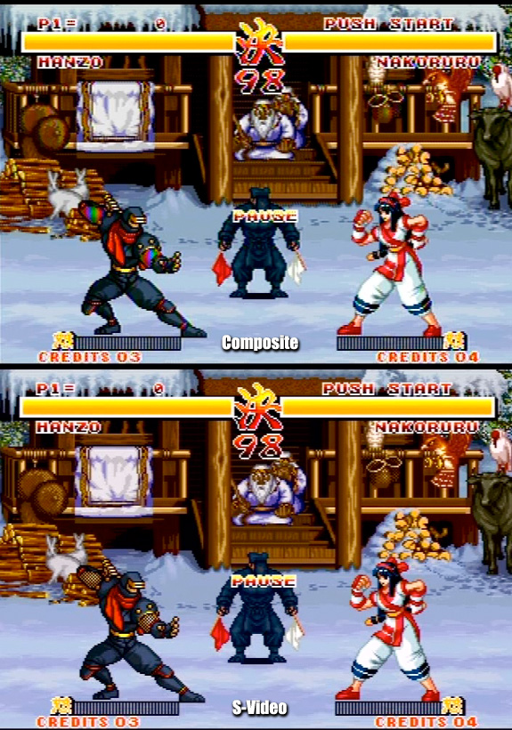
Above is the same screenshot via 2 different outputs. As you can see the Composite has the rainbow effect on Hanzo's sleeves. On the bottom is S-Video. You will notice that the picture is a lot clearer than the Composite. Also since this composite is a 3-6 you can probably imagine how bad the previous revision were via Composite.
Now you can always upgrade your video output via 2 ways, internal or external. If you want the best output possible it would have to be internally by adding an alternate video encoder and drilling holes on the back of your unit to add the jacks. The other method of course is external. You can create a module that uses the RGB lines via the rear AV socket on the Neo. Just remember that the AV socket has RGB lines that have passed through the internal Sony encoder then through some caps and resistors. You can still yield great results via the AV socket. In fact the above screen shot was done via our external video module. Very easy to make. We made it using a Neobitz-S, Sync Cleaner(Neo has a dirty Sync via the AV socket), project box, jacks as well as the 8 pin cable.
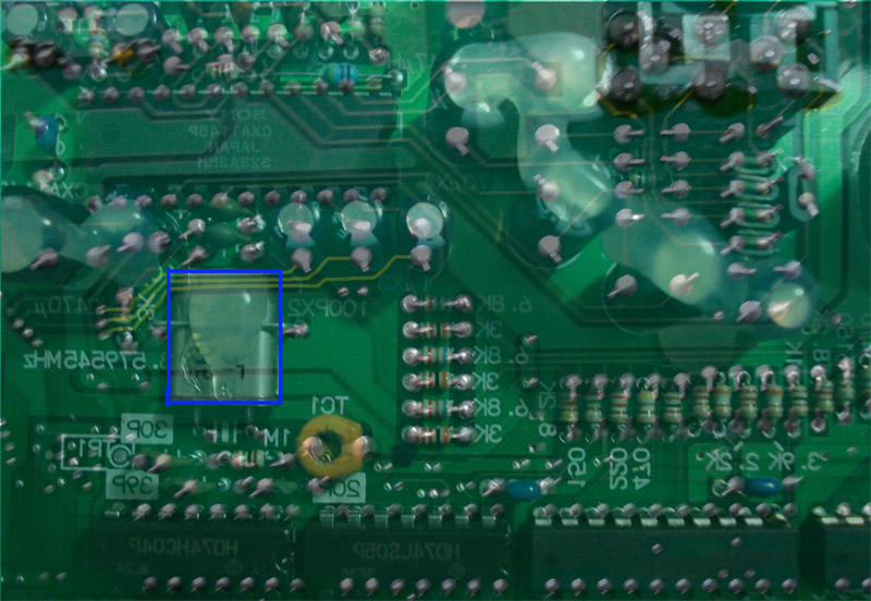
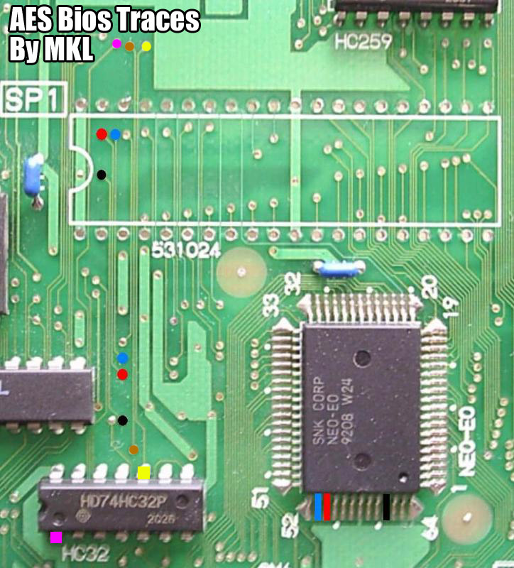
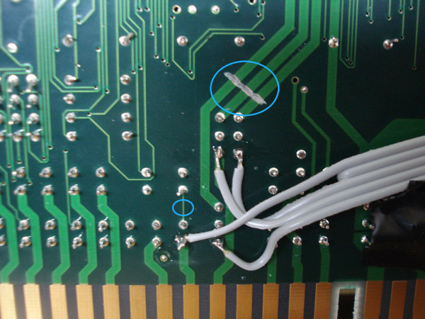
If you own a revision 3-6 Neo Geo AES then the picture is plagued by the dreaded clock interference. On a revision 3-6 SNK made some weird decision to make some kind of an expansion it seems for the RGB lines but never used it. The problem is that these additional routes run directly under a clock which sends out pulses which then show up on the screen as intereference.
Below is a ghosted picture so you can see what is actually hapening. The yellow lines are the RGB lines. As you can see they run right under the clock. The clock sends out pulses and since the traces are right under it it picks up the pulses as interference.
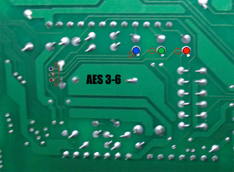
Above in the pic are the 3 traces that need to be cut on both ends, cut where the red outlines are. You can also remove the 3 traces completely which is what MKL recommends. You will need to sever the traces in 2 spots, right at the end and also right where they connect to the RGB lines. Doing so eliminates the on screen vertical lines. When I sever the traces I leave about a 1/16" gap to ensure nothing crosses over the cut.
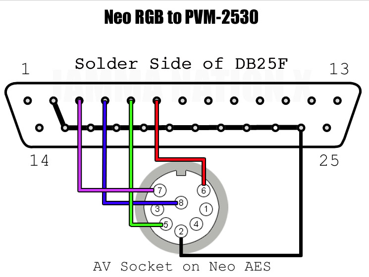
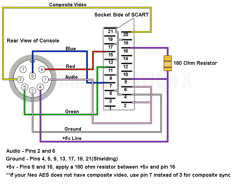
In the above pic is the wiring need to have your Neo Geo display on a Sony PVM RGB Monitor.
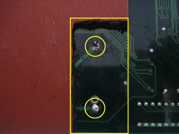
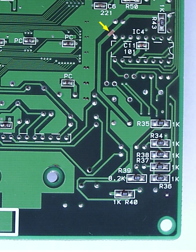
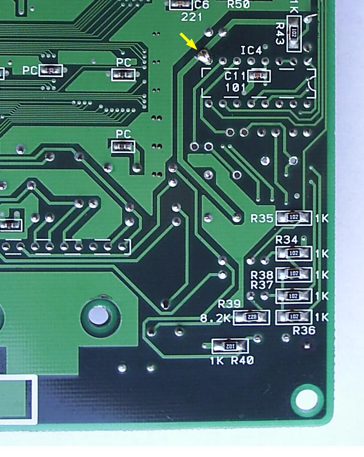
The above picture shows a broken trace that leads to the bios. Since this trace is broken it causes the AES to go into watchdog mode which constantly keeps resetting the CPU and making a click noise. The trace might not be very easy to see.
But as you can see below, if you hold up your board to a light source (the sun works best) you can clearly see the broken trace. I usually do this when fixing AES consoles to see if there are any broken traces. Of course keep in mind that you won't find the ones under chips.
This is also a good method to use if you are trying to find a spot to drill through a PCB.
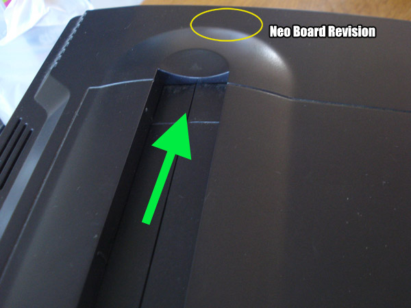
Your AES board version is visble through the cart slot. You will need a flashlight to see it, I am using an LED finger light. As you can see in the picture below look through the cart slot from the left side of the console while shining your flashlight into the console.
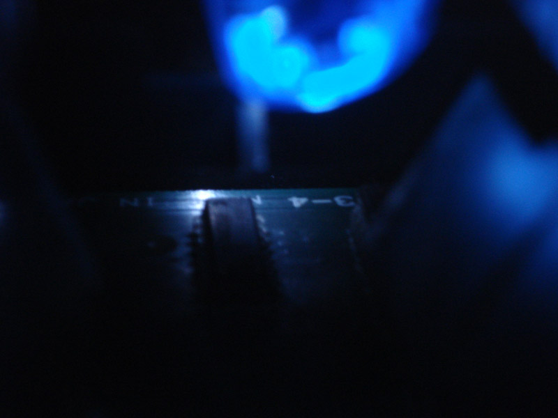
Here is a picture where you can clearly see the board version is 3-4. It will say either 3-3, 3-4, 3-5 or 3-6. If you do not see a number at all and the board color is a dark green, it indicates that your board version is either 1st gen (no daughter board) or 1st revision (With Daughterboard).
If your New Style Stick isn't functioning properly it might be due to the IC inside the stick which makes it different from the old style stick. I don't understand why SNK felt they had to change the technology in the stick since it's not needed.
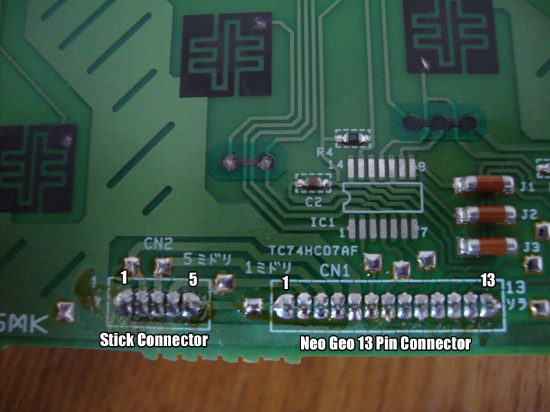
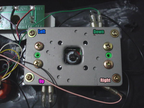
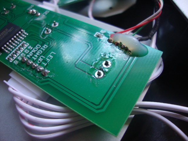
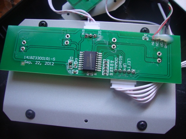
This is a picture of the PCB inside the New Style Stick with the IC removed. Below is the Pinout.
Stick Connector:
Pin 1 - Ground (Brown)
Pin 2 - Up (Pink)
Pin 3 - Left (Black)
Pin 4 - Right (Blue)
Pin 5 - Down (Green)
13 Pin Connector:
Pin 1 - Down (Green)
Pin 2 - Right (Blue)
Pin 3 - Left (Black)
Pin 4 - Up (Pink)
Pin 5 - Ground (Brown)
Pin 6 - Select (Red)
Pin 7 - D Button (Orange)
Pin 8 - B Button (Yellow)
Pin 9 - D Button (Teal)
Pin 10 - Start (Purple)
Pin 11 - C button (Gray)
Pin 12 - A button (White)
Pin 13 - VCC +5v (Light Blue)
The IC inside the stick is a 74HC07 SMD type. It can be purchased online in various places for about $8 each. All this chip does is send a low signal to the specific line that is being grounded just like how a normal button works on an MVS/AES. In the normal open position a button reads high, when the button is pressed and connects to ground it then reads low and the PCB activates that command. If the IC fries for some reason you could easily remove it and just bridge the connections to the buttons to fix the problem.
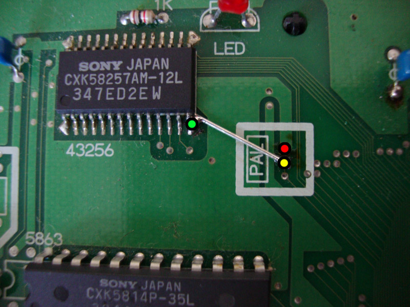
If you have accidentally cut the 3 traces by pin #2 during an AES bios install, here are where those 3 traces go to. Thanks MKL.
In the picture below is a 3-6 board revision, this is for 3-6 only. For NTSC, simply connect the green point to the yellow. For PAL, simply connect the red to the yellow. Don't forget that you will need to also change the colorburst crystal (4.43mhz for PAL and 3.57mhz for NTSC) with the correct frequency to fully convert the console to PAL or NTSC.
This info is taken from NEO-AES3-6 and NEO-AES3-4 revision boards and should be valid for all boards that have the bios to the right of the cart slot. The older board NEO-AES which has the bios above the cart slot is partly different.
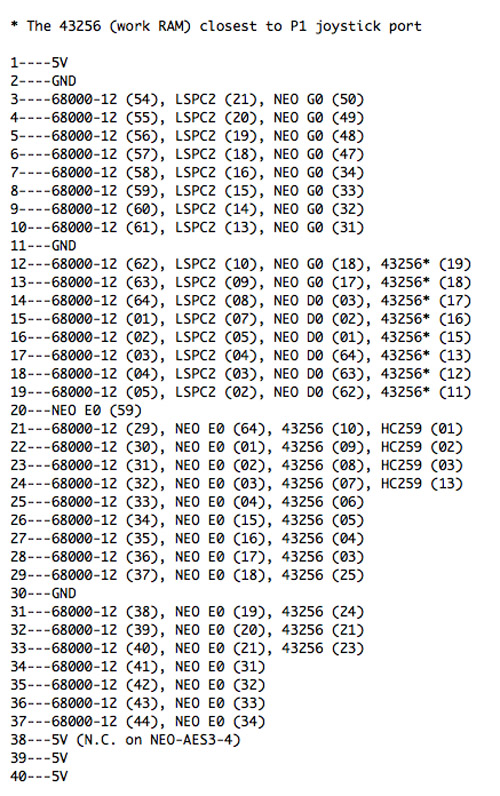
Info Courtesy of MKL
C2 and D2 signify the location of the RAM on the board. The Work RAM connections are to the 68k CPU.
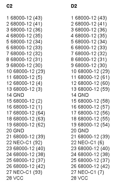
Info Courtesy of MKL
This is the pinout between the PROG board cart slot on the AES and the YM2610. If you are experiencing screeching audio or missing sounds check for continuity with these.
Taken from a 1st Gen AES
A32 - LS74-P3 (2,6) -> NEO-PCM (23)
A33 - YM2610 (33) -> NC?
A34 - YM2610 (48) -> NEO-PCM (48)
A35 - YM2610 (49) -> NEO-PCM (49)
A36 - YM2610 (50) -> NEO-PCM (50)
A37 - YM2610 (51) -> NEO-PCM (51)
A38 - YM2610 (52) -> NEO-PCM (53)*
A39 - YM2610 (53) -> NEO-PCM (54)*
A40 - YM2610 (54) -> NEO-PCM (55)*
A41 - YM2610 (55) -> NEO-PCM (56)*
A42 - YM2610 (41) -> NEO-PCM (57)
A43 - YM2610 (42) -> NEO-PCM (53)*
A44 - YM2610 (43) -> NEO-PCM (54)*
A45 - YM2610 (44) -> NEO-PCM (55)*
A46 - YM2610 (47) -> NEO-PCM (56)*
A47 - YM2610 (46) -> NEO-PCM (63)
B32 - YM2610 (17) -> NEO-PCM (28)
B33 - YM2610 (16) -> NEO-PCM (29)
B34 - YM2610 (15) -> NEO-PCM (30)
B35 - YM2610 (14) -> NEO-PCM (34)
B36 - YM2610 (13) -> NEO-PCM (35)
B37 - YM2610 (12) -> NEO-PCM (36)
B38 - YM2610 (11) -> NEO-PCM (37)
B39 - YM2610 (10) -> NEO-PCM (38)
B40 - YM2610 (23) -> NEO-PCM (39)
B41 - YM2610 (22) -> NEO-PCM (40)
B42 - YM2610 (35) -> NEO-PCM (41)
B43 - YM2610 (36) -> NEO-PCM (42)
B44 - YM2610 (37) -> NEO-PCM (43)
B45 - YM2610 (38) -> NEO-PCM (44)
B46 - YM2610 (20) -> NEO-PCM (45)
B47 - YM2610 (21) -> NEO-PCM (46)
Ratings are for out of the box RGB not fixed RGB.
1st Version (~3-1)
Rating - B
RGB Fix - Replace 100uf caps with 470uf value (10v is best fit). You do not need to replace the 68ohm resistors with 75ohm since they aren't 1% resistors but you can replace them for good measure.
1st Revision (~3-2) w/daughterboard
Rating - B
RGB Fix - Same as 3-1.
2nd Revision (3-3)
Rating - C
RGB Fix - Replace 100uf caps with 470uf value (10v is best fit)*, The 3-3 has a low output RGB. If you plan to mount an internal encoder for Component video, you will need to perform an RGB bypass if you plan to use the RGB output from the AV socket, if not the RGB picture will be extremely dim.
3rd Revision (3-4)
Rating - C
RGB Fix - Same as 3-3.
4th Revision (3-5)*
Rating - A (Non-Checkerboard) B (Checkerboard)
RGB Fix - Board version 3-5 is an odd one. There is a known checkerboard problem via RGB BUT not all 3-5 consoles suffer from the checkerboard pattern. If yours has the checkerboard pattern then an RGB bypass is needed.
5th Revision (3-6)*
Rating - B-
RGB Fix - Board version 3-6 suffers from vertical lines in picture. This is caused by the RGB lines running under the clock. A simple cutting of the 3 extra traces fixes the problem. If not for the vertical line problem, the 3-6 would have an A rating for it's RGB.
*Revision 3-5 and 3-6 are the two revisions where composite video is on both Pin 3 and 7 of the AV socket whereas 3-1 to 3-4 have composite video on Pin 3 and Composite Sync on Pin 7.
Please refer to the tutorials to perform the RGB bypass and upgrades for each revision.
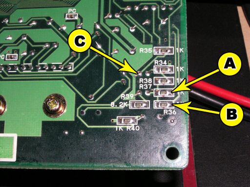
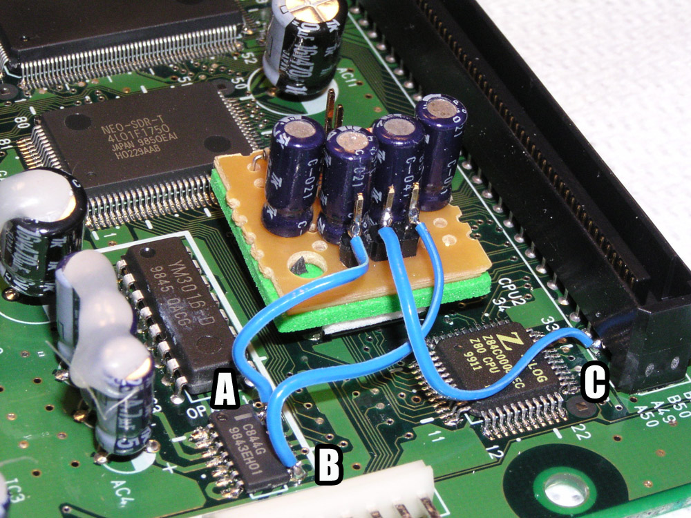
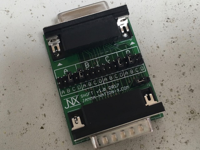
You will need to tap the A, B and C signals As shown in the photo. It's best to remove the two resistors before tapping the signal.
Tap the signals from the right side pad for A and B. C goes to the left pin of the pair shown.
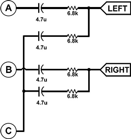
You will now need to build the above circuit using 4 x 4.7uf electrolytic capacitors and also 4 x 6.8k resistors. The easy way to look at the schematic is that Signal C goes to both left and right channels so when you build your circuit it's easiest to have Signal C in the middle.
Info Courtesy of Jeff Kurtz of Neobitz.
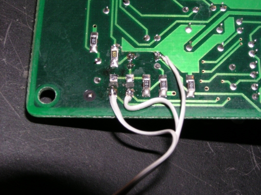
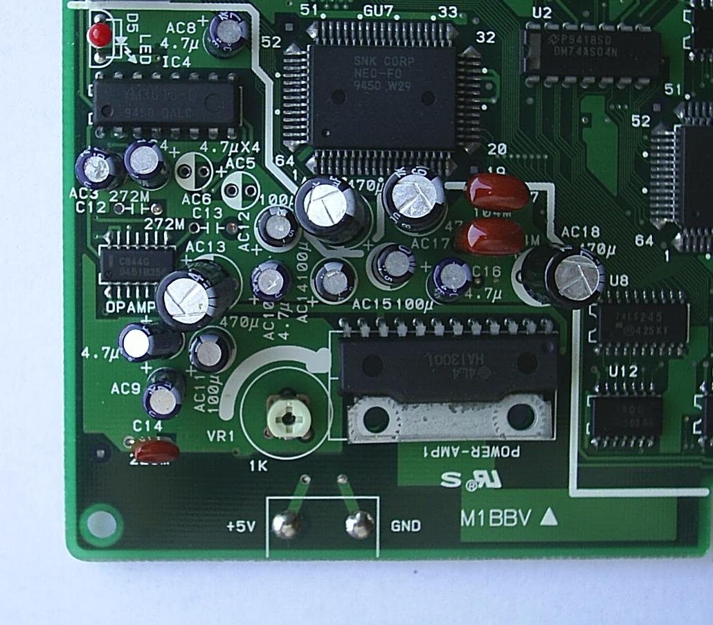
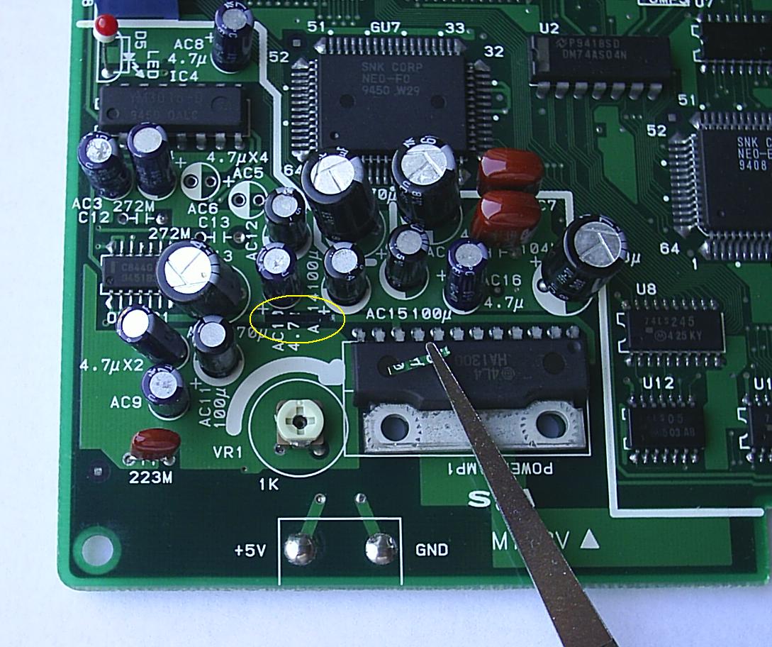
You will need to tap the A, B and C signals As shown in the photo. This is the underside of the board right behind the audio amp in the lower left of the board.
You will now need to build the above circuit using 4 x 4.7uf electrolytic capacitors and also 4 x 6.8k resistors. The easy way to look at the schematic is that Signal C goes to both left and right channels so when you build your circuit it's easiest to have Signal C in the middle.
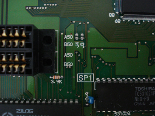
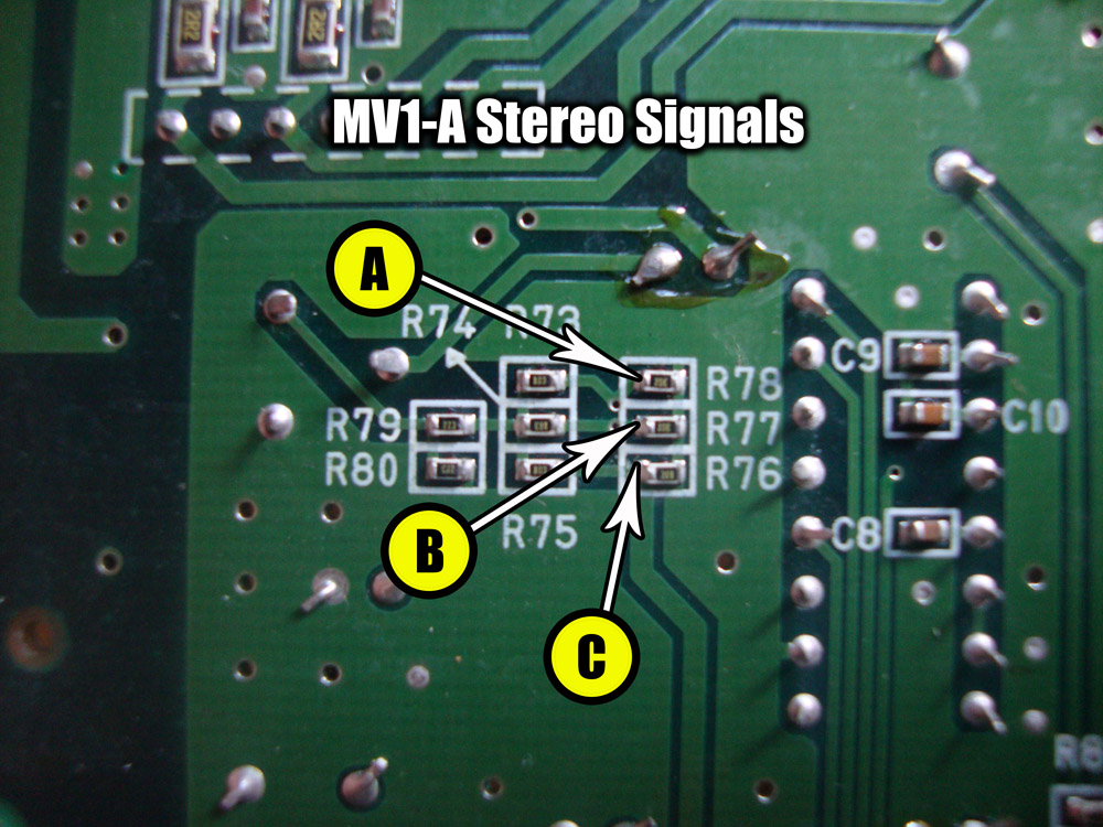
You will need to tap the A and B signals directly from the C844G chip. Signal A is tapped from pins 13 and 14, Signal B is tapped from pins 8 and 9. Signal C is taken from the back board connector A50.
You will now need to build the above circuit using 4 x 4.7uf electrolytic capacitors and also 4 x 6.8k resistors. The easy way to look at the schematic is that Signal C goes to both left and right channels so when you build your circuit it's easiest to have Signal C in the middle.
Info Courtesy of Jeff Kurtz of Neobitz.
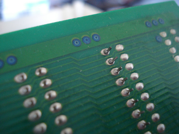
In the above picture is the most common problem found in MVS carts, a cracked solder joint. These cracks can cause all sorts of problems with your MVS cart from sound to graphics to just not running and resets.
Whenever your cart displays bad graphics or sound this is one of the things you should be looking for. Just simply resolder the joint and all will be well. You can see a ring on each of the 4 joints. If you see these rings it usually means the join is about to crack.
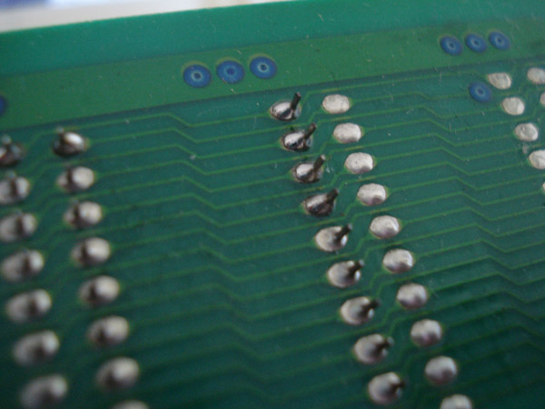
This is what the joints look like when fixed.
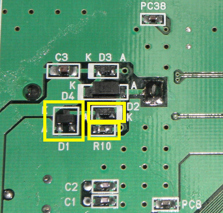
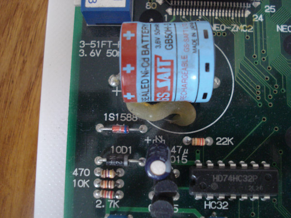
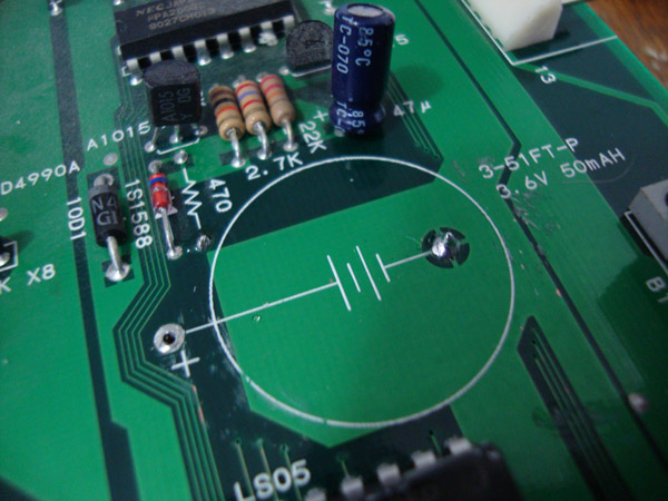
To disable the charging circuit on the MV1AX, remove the components highlighted in the picture. D1, D2 and R10.
To disable the charging circuit on the MV1B, remove the components highlighted in the picture.
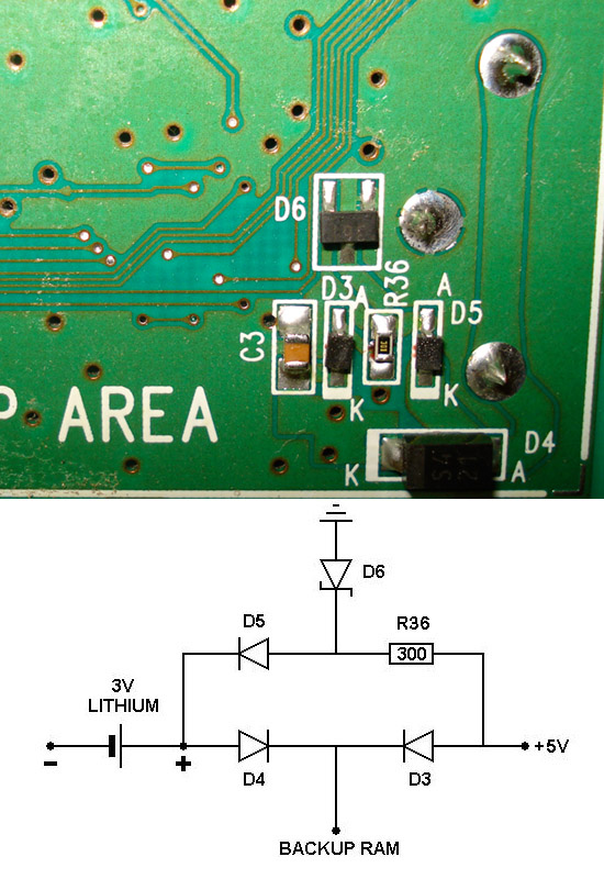
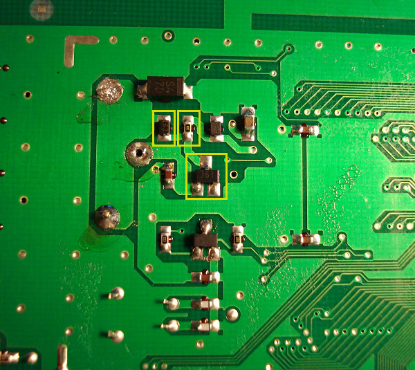
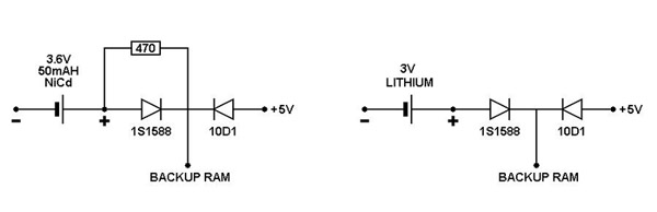
In the above picture is the battery charging circuit schematic. You will need to remove R36, D5 and D6. Then just desolder the old battery.
Schematic courtesy of MKL
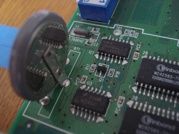
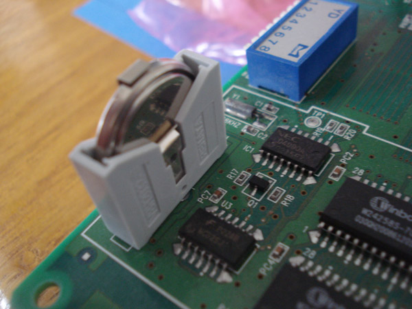
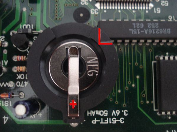
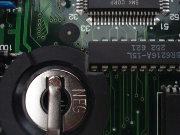
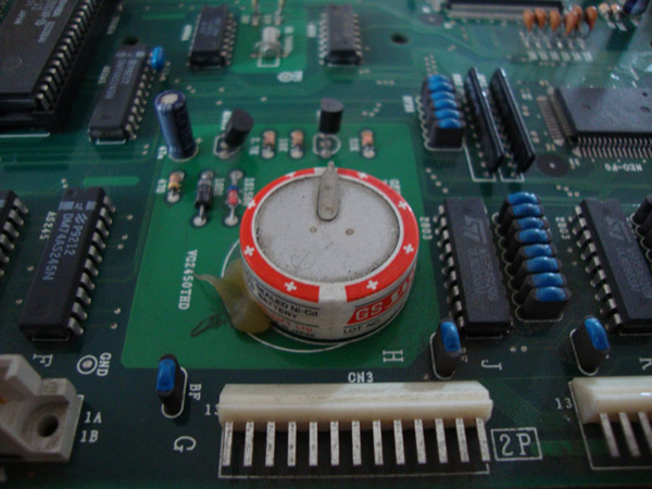
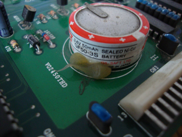
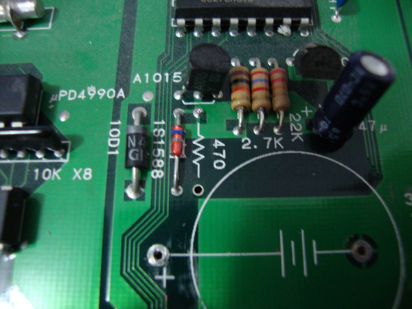
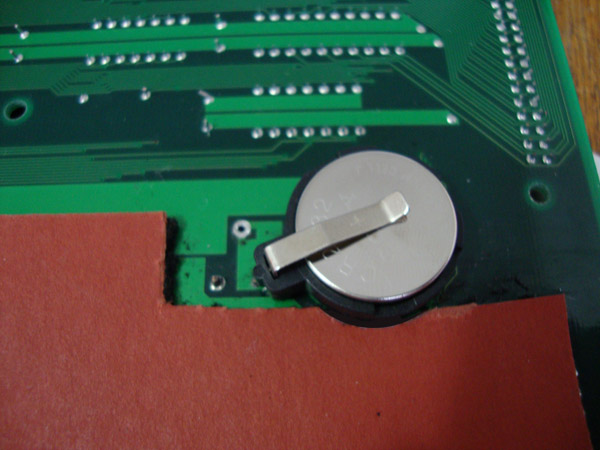
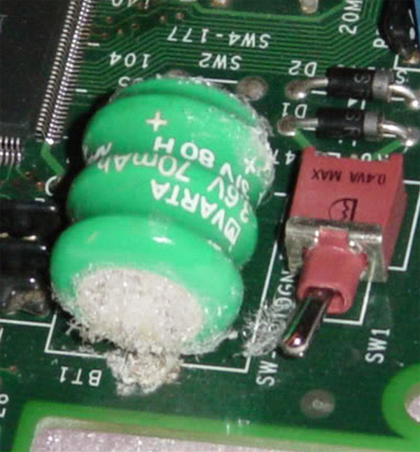
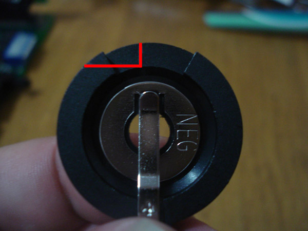
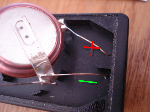
In the above picture is the battery found on an MV1C. Since most users of the MV1C usually don't leave their cabs on the battery doesn't charge properly and ends up deleting any backup data such as high scores and settings.
SNK used a custom battery for this board and no one carries a direct replacement for a battery holder. We will be removing the stock battery and in it's place will be a vertical battery holder which uses a standard CR2032 coin cell 3V Lithium battery.
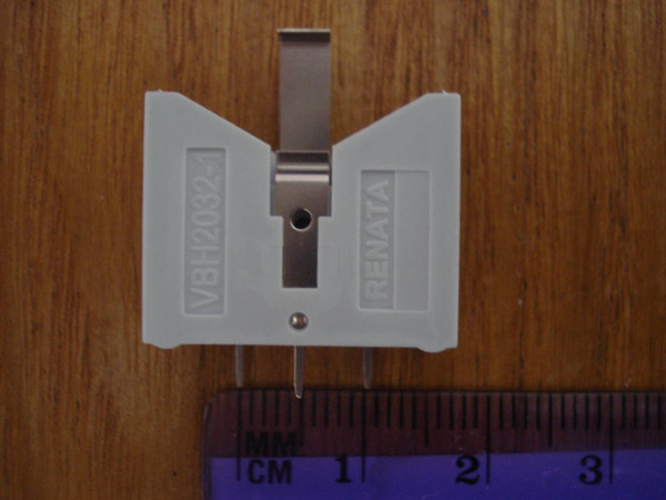 In the above picture is a Renata VBH2032-1 which can be purchased at mouser.com. As you can see the left and right pins measure 10mm apart. On the MV1C battery the pins are 15mm apart meaning you will need to extend the legs somehow in order for them to fit properly.
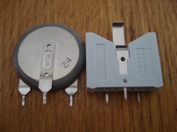 In the above picture is the two side by side.
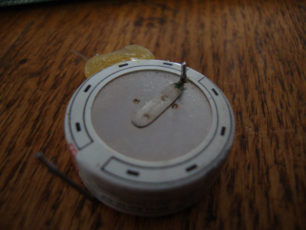
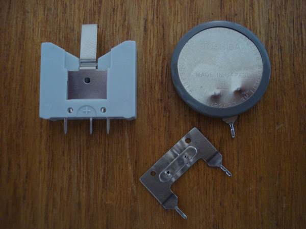 The easiest and cleanest method I have found is to remove the double legged lead from the stock battery. Just use a pair of pliers to take it off the battery.
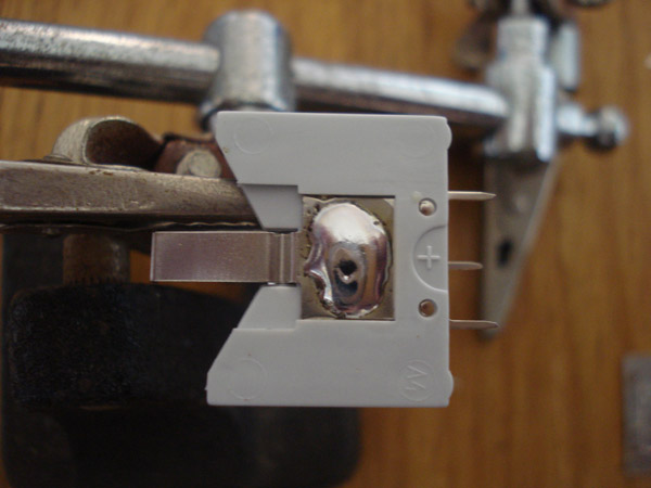 On the positive side of the battery holder add some solder, you will need to add quite a bit. Just add enough to where the solder is higher than the plastic on the sides of it.
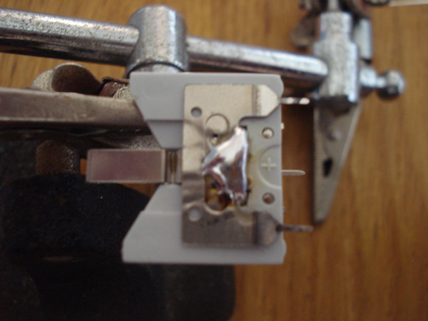 Place the 2 legged battery lead on to the solder glob you just made and line it up like so. Using your soldering iron heat up the solder underneath the lead and add some to the top as well to create the joint. Snip off the 2 legs from the battery holder you won't be using.
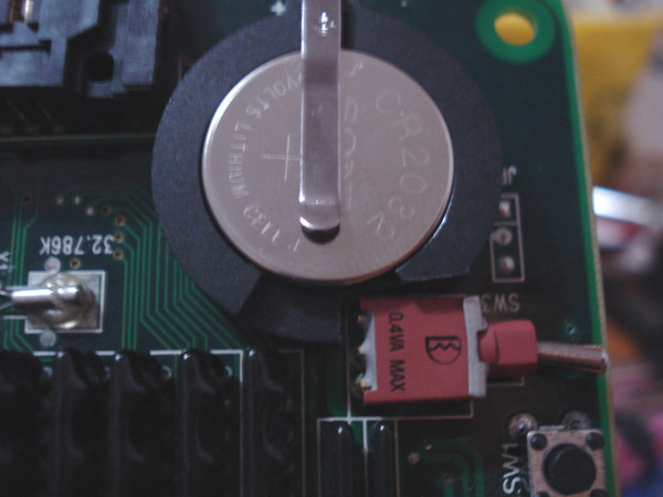
 That's it, now just solder it into the empty holes that were there and you will end up with this. Make sure the positive side of the battery is facing the left side of the board, Positive out and Negative in.
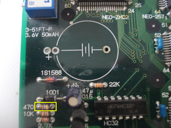
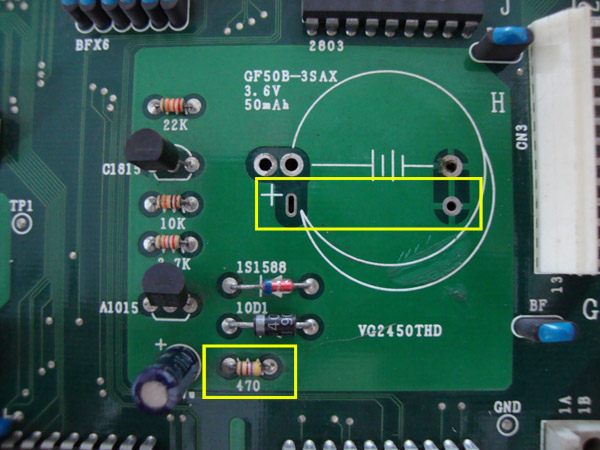
In the above picture is the battery charging circuit schematic. You will need to remove the 470ohm resistor.
Schematic courtesy of MKL
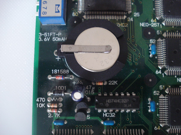
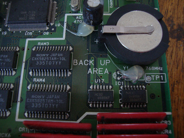
In the above picture is the battery found on an MV2F which is on the upper left side of the board. Since most users of the MV2F usually don't leave their cabs on the battery doesn't charge properly and ends up deleting any backup data such as high scores and settings.
We will be removing the stock battery and in it's place will be a standard CR2032 coin cell 3V Lithium battery. You can use other model coin cell batteries with higher capacities if you want.
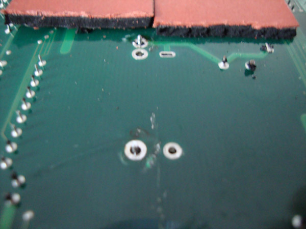
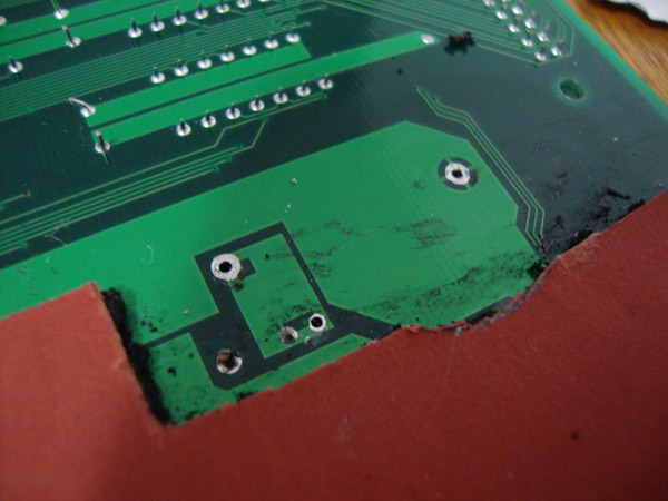
 In the above picture is the bottom side of the board directly under the stock battery. The area is usually covered with a black foam covered in a redish thick paper. Remove the foam in the yellow area to get to the 2 solder points for the battery. Desolder the old battery and remove it.
 In the above picture is the 470ohm resistor you need to remove. You can either cut the resistor off the board or desolder it if you want to. Then solder in your coincell battery holder into the 2 holes where the old battery used to be.
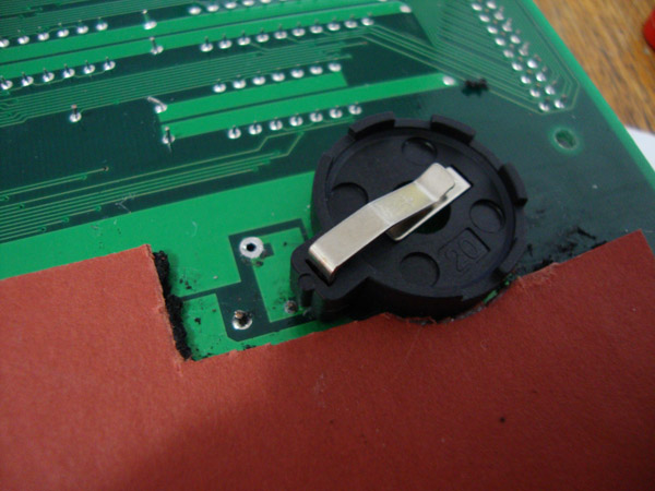
 Once you have soldered in your battery holder go ahead and put the new battery in. Make sure the flat (Positive) side is facing up. That's it. If you need the battery and socket we have it in the store for purchase.
In the above picture is the battery found on an MV1F and MV1FS which is on the upper right side of the board under the black plastic cover. Since most users of the MV1F usually don't leave their cabs on the battery doesn't charge properly and ends up deleting any backup data such as high scores and settings. We will be removing the stock battery and in it's place will be a standard CR2032 coin cell 3V Lithium battery. You can use other model coin cell batteries with higher capacities if you want.
In the above picture is the bottom side of the board directly under the stock battery. The area is usually covered with a black foam covered in a redish thick paper. Remove the foam in the yellow area to get to the 2 solder points for the battery. Desolder the old battery and remove it.
In the above picture is the 470ohm resistor you need to remove. You can either cut the resistor off the board or desolder it if you want to.
Before you solder in your battery holder, you will need to cut a notch out to make the battery holder sit flush with the board. I personally use a Dremel but you can cut it with any other tool. Once the notch is cut out go ahead and solder the holder in. Make sure the positive side is towards the right edge of the board. After you solder it in, go ahead and put the new battery in. Make sure the flat (Positive) side is facing up. That's it.
If you need the battery and socket we have it in the store for purchase under Arcade Accessories. The ones found in the store do not require cutting, they are small enough to fit without it.
In the above picture is the battery charging circuit found on the underside of the MV1-FZ under the black foam pad. Since most users of MVS boards don't usually leave our cabs on the battery doesn't charge properly and ends up deleting any backup data such as high scores and settings.
To disable the charging circuit remove parts D1, D2 and R3 as shown above.
Desolder the old battery and remove it and then replace with the new socket and install your new battery.
If you need the battery and socket we have it in the store for purchase under Arcade Accessories.
In the above picture is the backup battery on an MV-4T (4 slot MVS board). Keep in mind there are two versions of 4 slots. The 4T is the newer version.
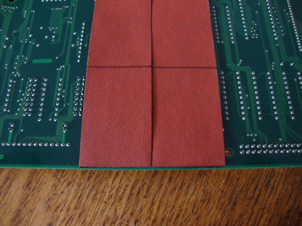
In the above picture is the foam pad on the underside of the board where the backup battery solder spots are. Simply mark a line roughly 2.5" from the outside edge of the foam pad.
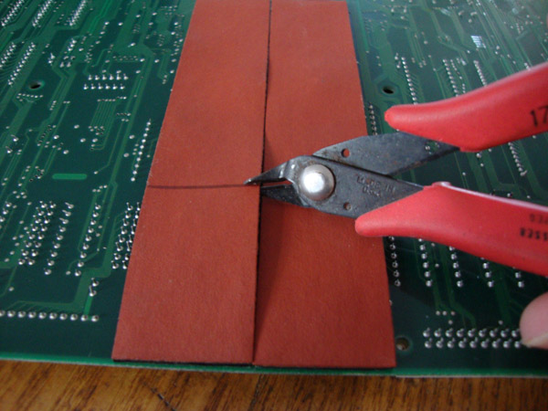
I use wire snips and cut along the line. Make sure you are only cutting the red paperbacking of the foam with the wire cutters. Once you cut all the way across simply remove the red paper backing and remove the black foam covering the area. Do not use anything abrasive as there are some traces under the foam.
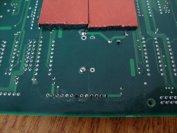
This is what it looks like with the foam cleaned off.
Now you will need to desolder the battery. You can use a solder sucker or desoldering wick, I prefer a desoldering iron.
Now flip the board back over and you will notice that SNK used some glue or silicone adhesive to hold the battery. You may need to pry the battery up if the glue is still holding.
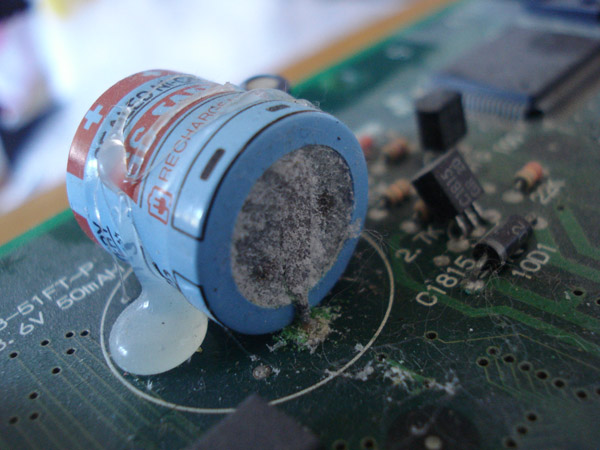
Here you can see that the battery was at a very early stage of leaking. It's a good thing I took it off.
Now you need to disable the charging circuit. In the above picture you will see on the bottom left a 470ohm resistor. Simply remove the 470ohm resistor to disable the charging circuit. The highlighted area above is where you will be mounting the coin cell battery holder.
This is what it should look like with the new coin cell holder installed. You could also install the battery holder on the underside of the board to make for easy swapping in the future since you wouldn't need to take the boards apart.
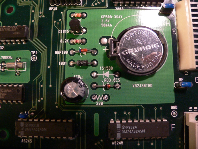
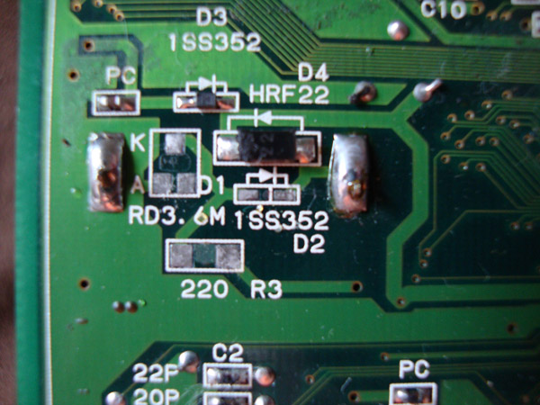
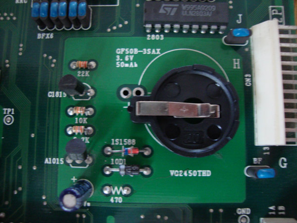
In the above picture is the backup battery on an MV-4FS (4 slot MVS board). According to user Hairy Otter of the Neo-Geo.com forums, you will need to remove the 220ohm resistor as well as the diode labeled 1S1588 and HRP100. After removing them, place the 1S1588 diode in the spot where the HRP100 used to be as shown in the picture .
Battery holder shown is the standard 20mm single cell type with a CR2032 battery.
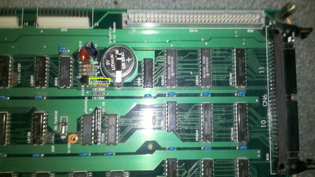
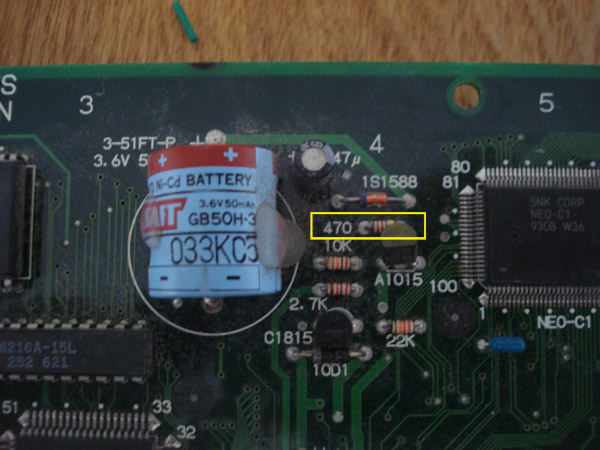
In the above picture is the 470ohm resistor to remove to disable the charging circuit. Picture provided by Jaelus.
This is what it should look like with the new coin cell holder installed. You could also install the battery holder on the underside of the board to make for easy swapping in the future since you wouldn't need to take the boards apart.
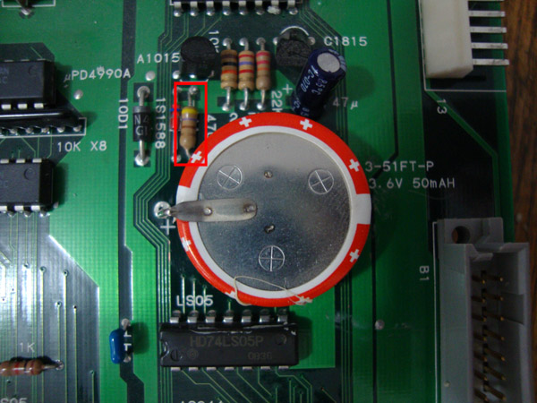
In the above picture is the battery on the MV6. You will need to remove the highlighted 470ohm resistor by desoldering it, you can not cut it if you want to reverse mount the battery holder as you will need the hole for the resistor free of solder.
 In the above picture is what it will look like with the battery and resistor removed.
 In the above picture is the underside with the resistor and battery removed. You will need to trim the hard paper backing to fit the battery holder.
 Now slide the positive leg of the battery holder into the hole where the resistor used to be, the negative leg goes into the hole where there negative leg of the battery was.
 Now solder them in.
 Then just put the CR2032 in the battery holder. That's it.
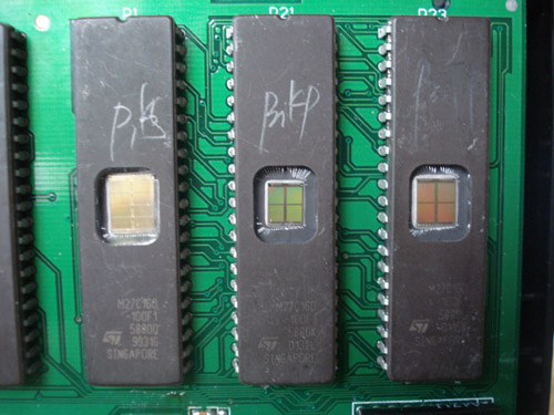
In the above picture is the most common thing found in a bootleg cartridge, a windowed eprom chip.
But keep in mind there are some official repairs made by SNK using them.
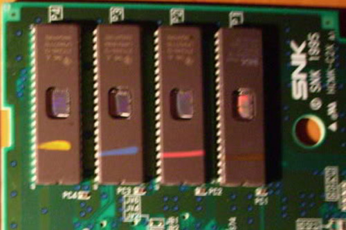
Usually during an SNK repair they used colored pencils to mark the chips that were repaired.
Most common is 3 colors - pink, blue and orange.
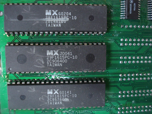
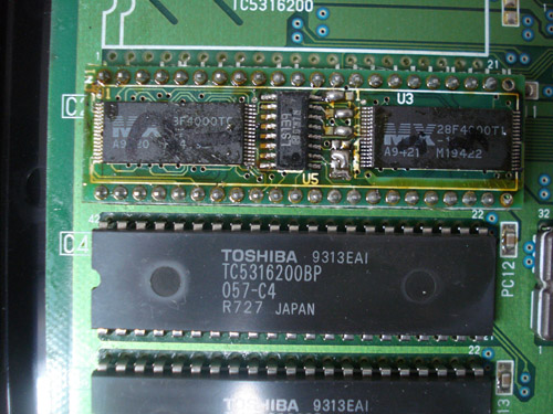
In the above picture are MX Flash chips, always found in boots and never in an offical cart. Official cart use either Toshiba or Sharp chips.
In the above picture is a picture of a piggy backed MX flash chip. These SMT MX flash chips are sometimes in legit carts. Only one I have seen was in Samurai Shodown 5.
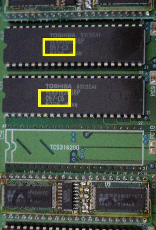
Highlighted in the above picture is the Neo Geo NGH number. When you compare this number to the master list it tells you what game the roms belong to. In this picture it is from a Puzzle De Pon bootleg cart.
NGH #057 belongs to World Heroes 2.
If you're cart has conflicting NGH numbers it is most likely a boot.
The best place to check your cart is to visit is MVS Scans. The site is runned by neo-geo.com's member ack. He has tons of scans of MVS labels and boards.
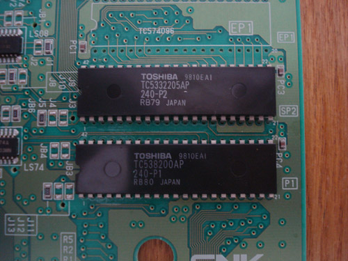
In the above picture are the P Chips, they contain the actual game code.
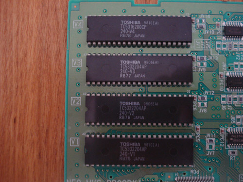
In the above picture are the V Chips, they contain the sound samples.
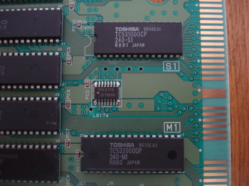
In the above picture are the S1 and M1 Chips. The S1 chip contains certain details of the game such as health bars, fonts and others. The M1 chip controls the sound chip.
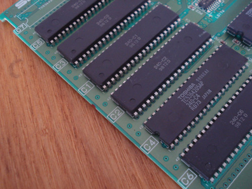
In the above picture are the C Chips, they contain the graphics and sprites for the game.
In your Neo Geo MVS and AES cart there consists of many different chips.
This is to help you understand the main ones used for graphics, sound and program.
P rom is the chip used for the game code. This chip(s) can run at 16bit mode.
V rom is the chip used for the game sounds. This chip(s) can run only at 8 bit mode.
C rom is the chip used for the game graphics. This chip(s) can run at a max of 32 bit mode.
S rom is the chip used for the game details. This chip can only run in 8 bit mode.
M rom is the chip used for the sound control. This chip can only run in 8 bit mode.
Keep these notes in mind when repairing AES/MVS carts. Usually people use EPROMS to replace any bad chips in a cart. For example some MVS games have some V roms that are 4mb in size BUT they are able to run in 8 bit mode. People often try to replace them using a 27C322 since it's the same size chip BUT the 322 can only run in 16 bit mode so it is not a direct replacement. Instead it's easier to split the file into two files of 2mb each and using 27C160 chips instead.
This is the pinout between the PROG board cart slot on the MVS and the YM2610. If you are experiencing screeching audio or missing sounds check for continuity with these.
A41 - NC
A42 - NC
A43 - YM2610 (41) -> NEO-PCM (57)
A44 - YM2610 (42) -> NEO-PCM (58)
A45 - YM2610 (43) -> NEO-PCM (59)
A46 - YM2610 (44) -> NEO-PCM (60)
A47 - YM2610 (47) -> NEO-PCM (61)
A48 - YM2610 (46) -> NEO-PCM (63)
A49 - YM2610 (16) -> NEO-PCM (38)
A50 - YM2610 (23) -> NEO-PCM (39)
A51 - YM2610 (22) -> NEO-PCM (40)
A52 - YM2610 (35) -> NEO-PCM (41)
A53 - YM2610 (36) -> NEO-PCM (42)
A54 - YM2610 (38) -> NEO-PCM (44)
A55 - YM2610 (20) -> NEO-PCM (45)
A56 - YM2610 (21) -> NEO-PCM (46)
B41 - YM2610 (48) -> NEO-PCM (48)
B42 - YM2610 (49) -> NEO-PCM (49)
B43 - YM2610 (50) -> NEO-PCM (50)
B44 - YM2610 (51) -> NEO-PCM (51)
B45 - YM2610 (52) -> NEO-PCM (53)
B46 - YM2610 (53) -> NEO-PCM (54)
B47 - YM2610 (54) -> NEO-PCM (55)
B48 - YM2610 (55) -> NEO-PCM (56)
B49 - YM2610 (17) -> NEO-PCM (28)
B50 - YM2610 (16) -> NEO-PCM (29)
B51 - YM2610 (15) -> NEO-PCM (30)
B52 - YM2610 (14) -> NEO-PCM (31)
B53 - YM2610 (13) -> NEO-PCM (34)
B54 - YM2610 (12) -> NEO-PCM (35)
B55 - YM2610 (11) -> NEO-PCM (36)
B56 - YM2610 (10) -> NEO-PCM (37)
A calendar error is caused by one of three things.
1. The Battery
2. The Calendar Chip (D4990)
3. The Calendar Crystal (Usually it's a 32.767 khz).
If you turn on all the dipswitches then power on the system it will perform a work ram test which once in a while will clear up the error. After the work ram test turn the dips off then power the system back on.
If the you still get a calendar error after fixing the battery and crystal it could be the Calendar chip itself. First thing to check would be Pin 14 on the calendar chip. It should be getting +5v, if it isn't that's your problem. Check why your chip isn't getting the voltage it needs, maybe a cut trace.
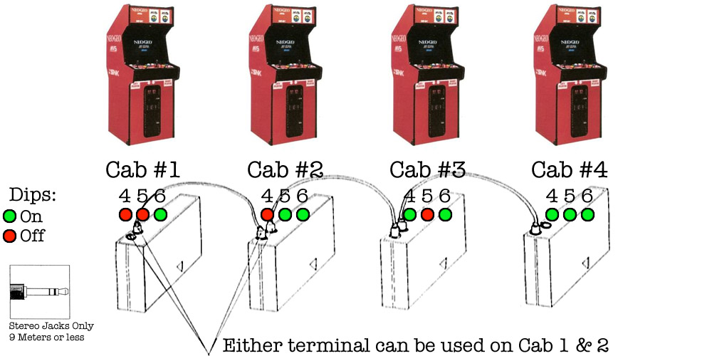
As shown in the picture above it is very simple. You will be using stereo headphone jacks to link the carts together. Remember to keep the length per cord to no more than 9 meters which is about 30 feet. Assign cab numbers by flipping the hard dips shown. For the first 2 cabs or boards you can use either link terminal on the cartridge.
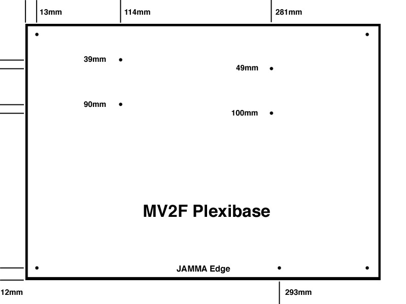
As shown in the picture above it is very simple. The Plexi I use is 15-7/8" x 11-1/2" and a 1/4" thick. You can buy plexi off ebay and the seller will cut it to the size you want. Depending on what color you choose you can get it for as low as $22 shipped. I use millimeters for the measurements in the picture since it's more precise. Follow the measurements and use a very small drill bit to make a pilot hole, I use a 1/16" bit then use a 1/8" bit to complete it. For the cart slots I only use 2 standoffs per slot. To complete the look I sand and buff the edges of the plexi. I hand sand it with 220, 320 then 600 grit and use my Dremel to buff with rubbing compound.
Keep in mind that these measurements are only for an MV2F and are different from an MV2 mobo which is longer than the MV2F.
Info provided by MKL
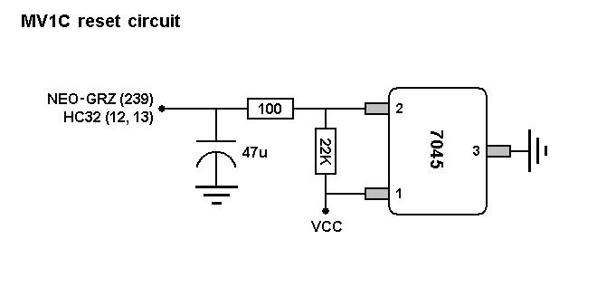
As shown in the picture above is the MV1C reset circuit. To perfom a reset you simply just need to ground pin 2 on the 7045 IC.
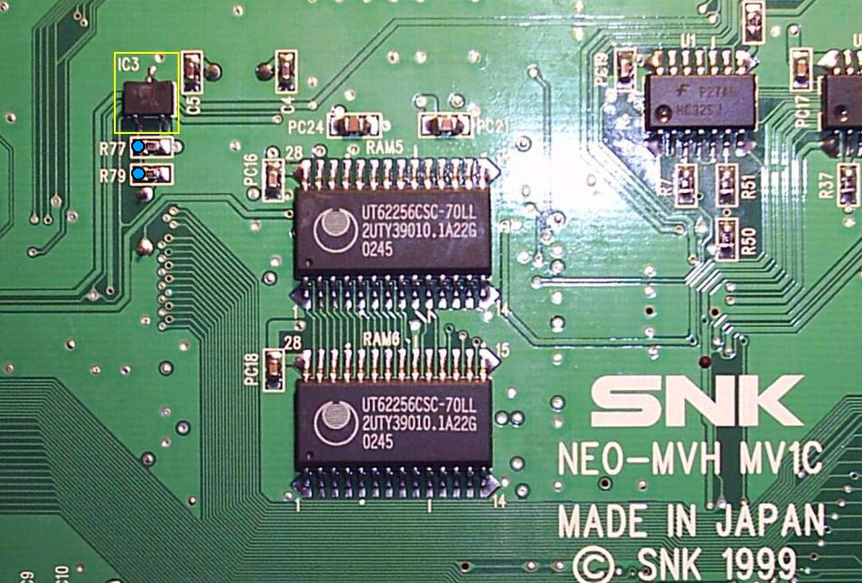
Easiest way to do this is by soldering to the left side of either R77 or R79 which connects to Pin 2 on the 7045 IC. Use a momentary switch with one leg connected to ground and the other leg to the left side of either point on the pic above.
.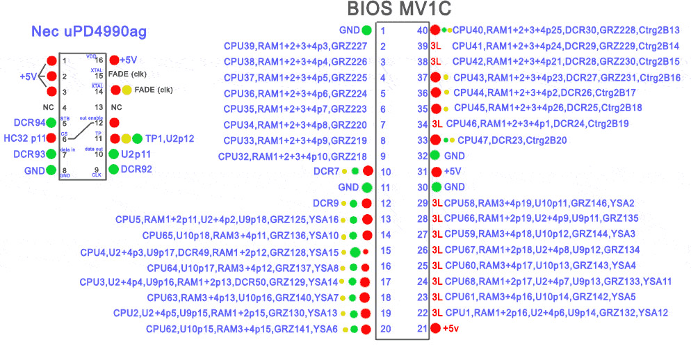
This is the full pinout for the MV1C bios. Use this info to fix your MV1C board. If your board is stuck in watchdog mode (constant clicking and flashing) check all connections to the bios. If any are broken, repair them then test.
Info courtesy of Distropia aka ocelete.
Info provided by MKL
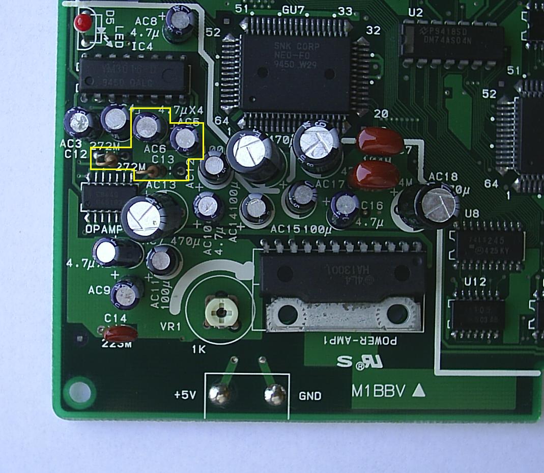
In the picture above is the sound circuit. Remove the 2 capacitors and 2 resistors indicated above. Keep the 2 resistors for later.
With them removed it should look like this.
Now cut the +12v trace shown above, you can either cut it or you can remove it as shown above.
On the underside of the board of the sound circuit, find this area and remove the coating from the trace using a knife or sharp object. I use an xacto knife and rub it gently on the trace to expose it.
Now make a solder bridge using the pin from the IC above.
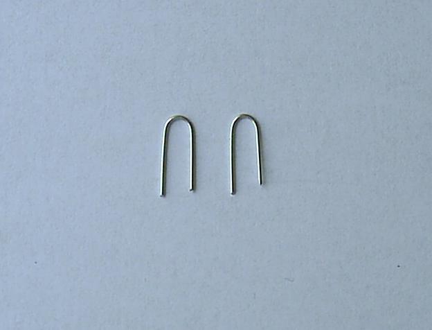
Now take 2 pieces of wire or use some resistor legs you have lying around and bend them like so.
Insert them in the holes where the capacitors used to be so they jump the connection.
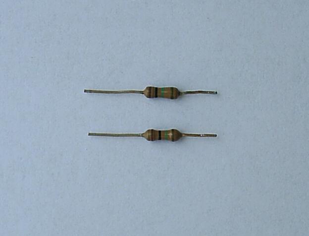
Now trim the 2 resistors you saved and cut them to this length.
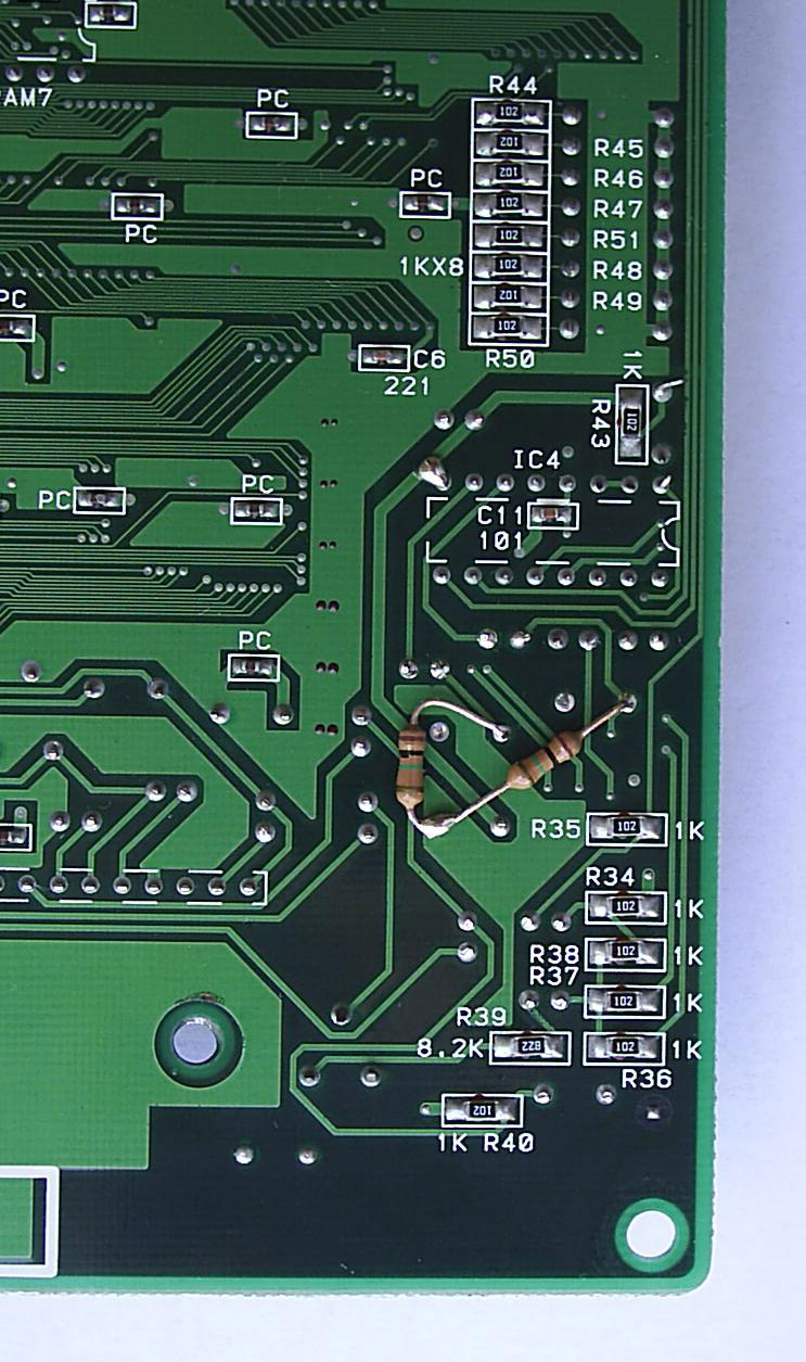
On the underside of the board. Place them like this.
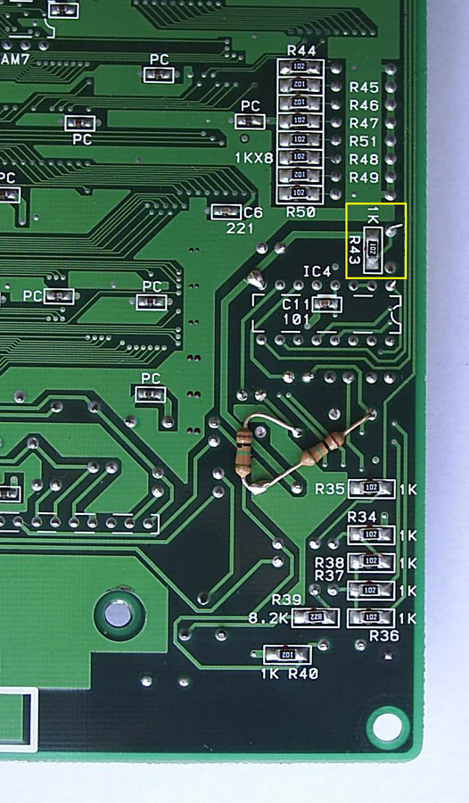
Now remove R43 as shown above.
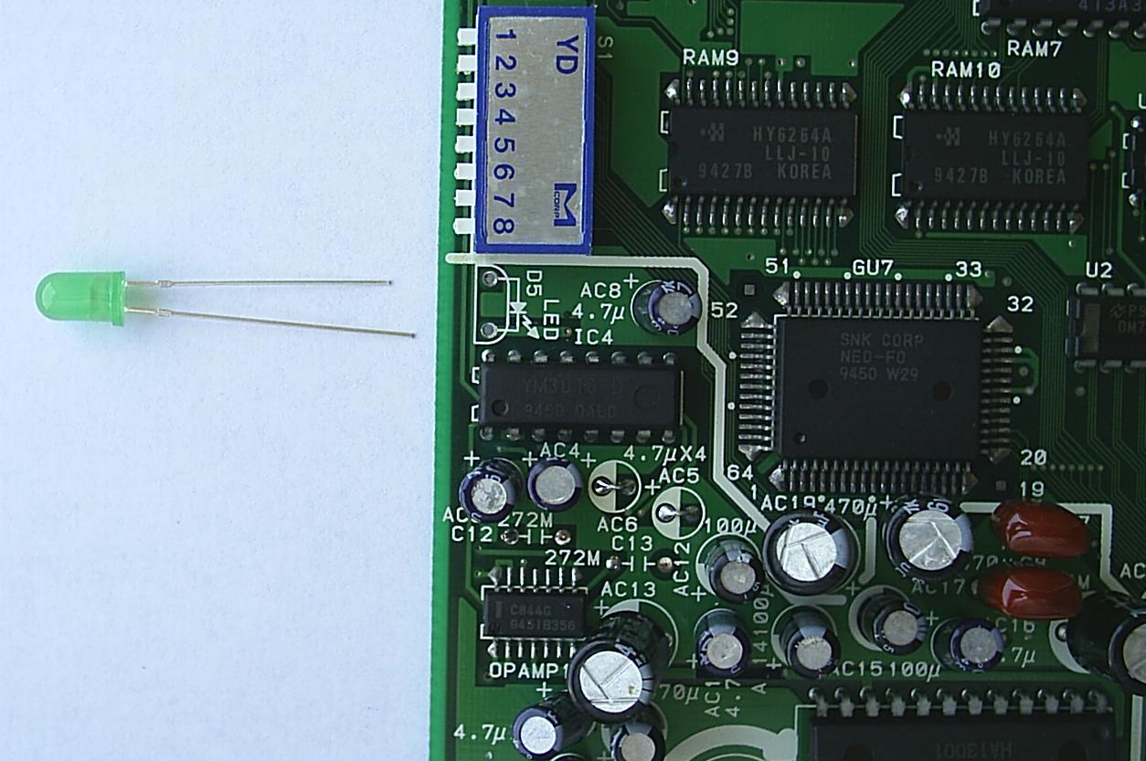
Now remove the old +12v LED and replace with a 3-5v LED.
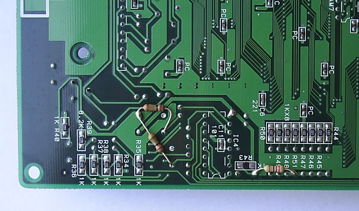
Now make a bridge to ground using the appropriate resistor for the color LED you chose.
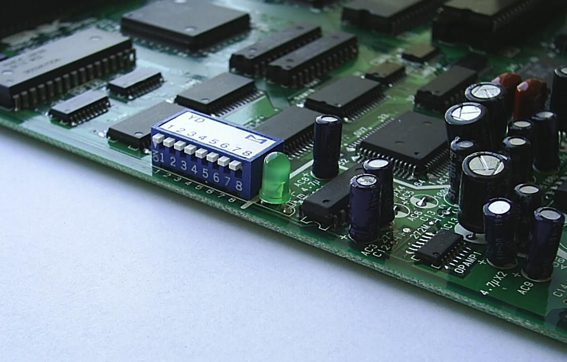
There you go, all done now. Keep in mind that if you supply the FZ with +12v after doing this mod you will have a scrambled picture so use only +5v. Sound will be available from pins 8 (Right) and 14 (Left) from the opamp IC. If you want true stereo sound you will need to build a small circuit. Schematic is in the FZ stereo tutorial.
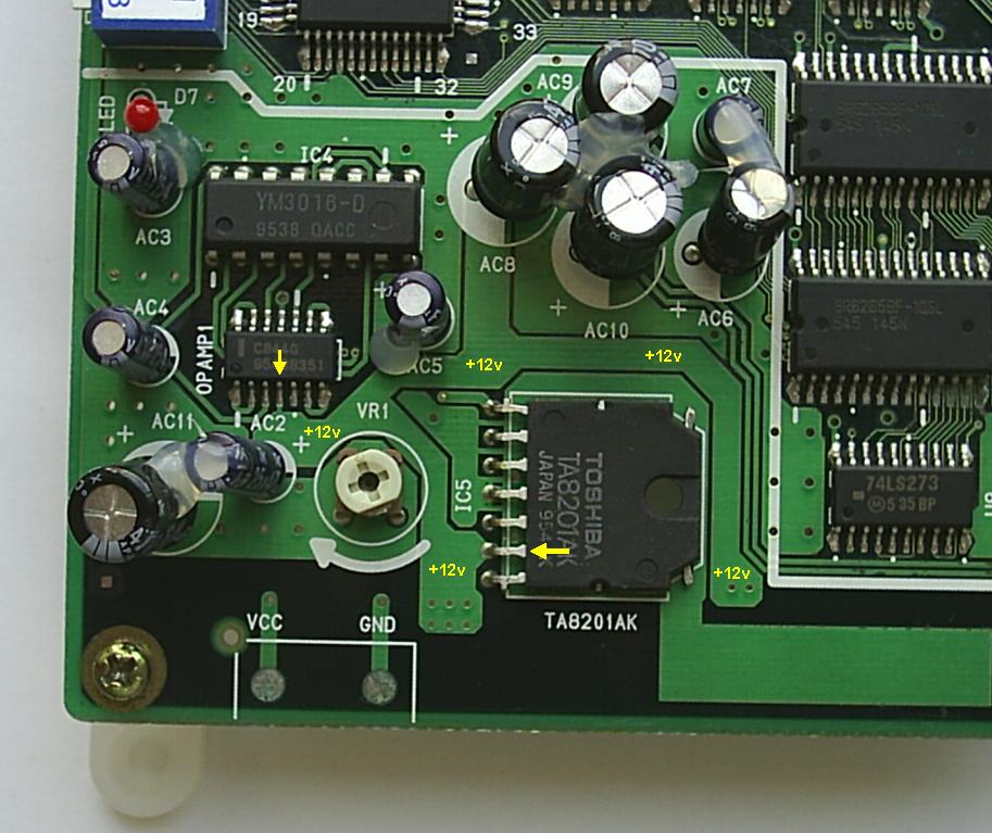
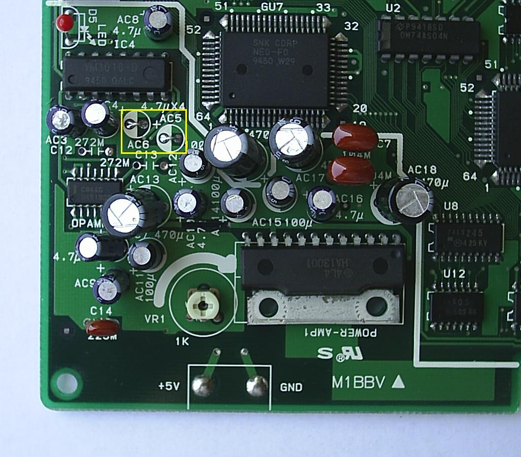
In the picture above is the sound circuit. Pin 4 on the C844G is the power input pin. This amp is able to run on a wide range of voltages including +5v.
You will need to sever the trace from the +12v first.
Next you will need to connect pin 4 to a +5v power source. Since pin 4 is connected to the capacitor directly below it, you can use this connection on the underside to connect it to a +5v source which is pin 3 of the YM3016.
Info is provided by MKL. Please remember that you will still need to build a small circuit for stereo sound. It is the same circuit found in the FZ stereo tutorial.
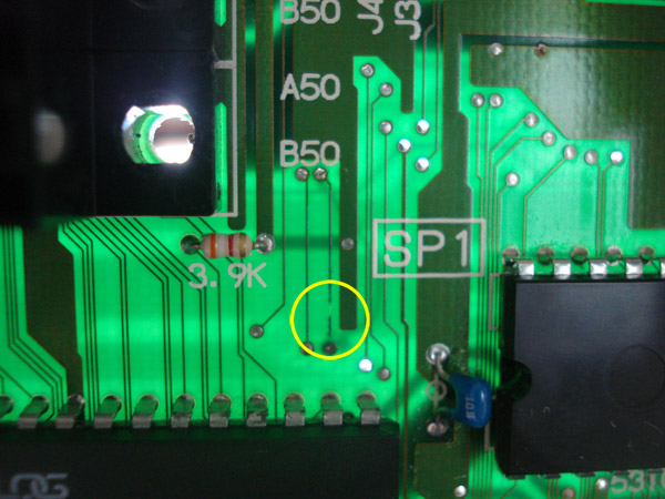
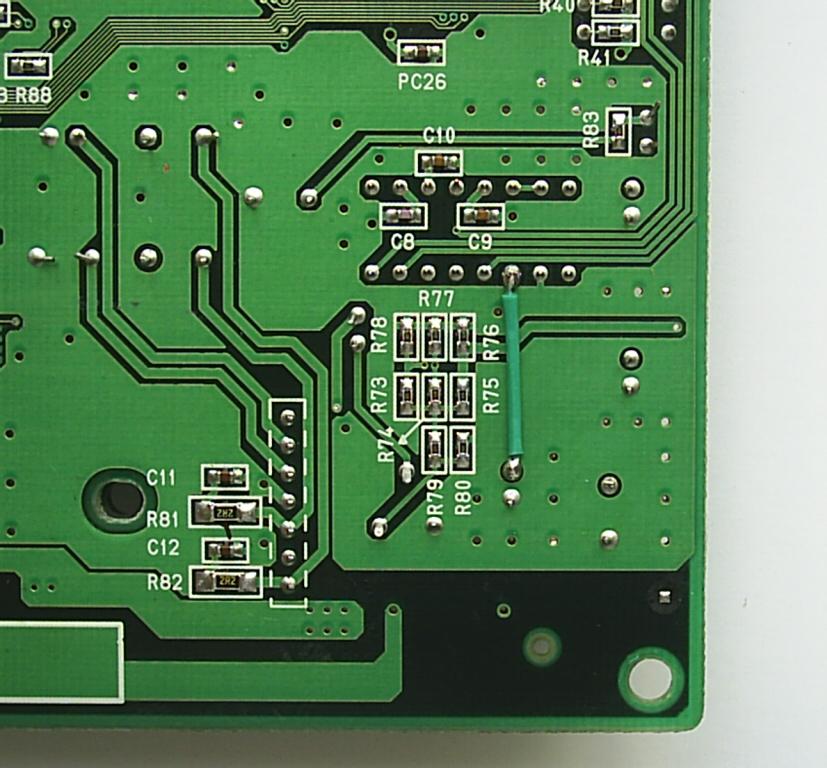
In the picture above is the underside of the sound circuit. Use ONE of any of the four bridges indicated in the picture. After this mod your MV1 will now be able to run on 5v only and also can still be used in a cab.
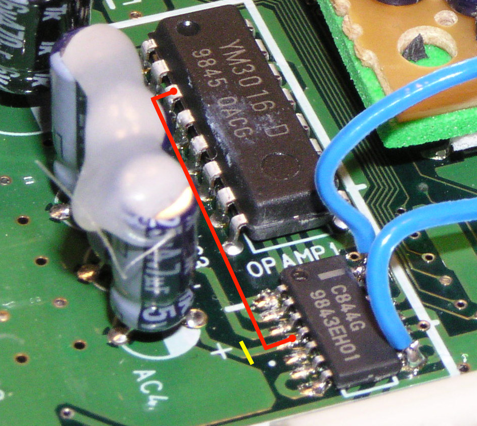
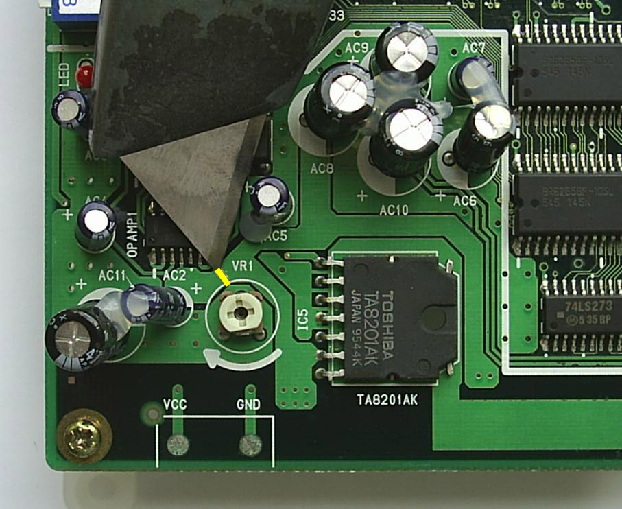
In the picture above is the C844G chip. All you need to do is cut the trace to pin 4 (Yellow Line) and join pin 4 to pin 3 on the YM3016 (Red Line) to supply the C844G with +5v for audio.
Info provided by MKL
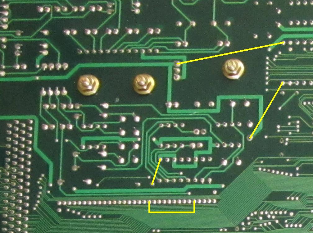
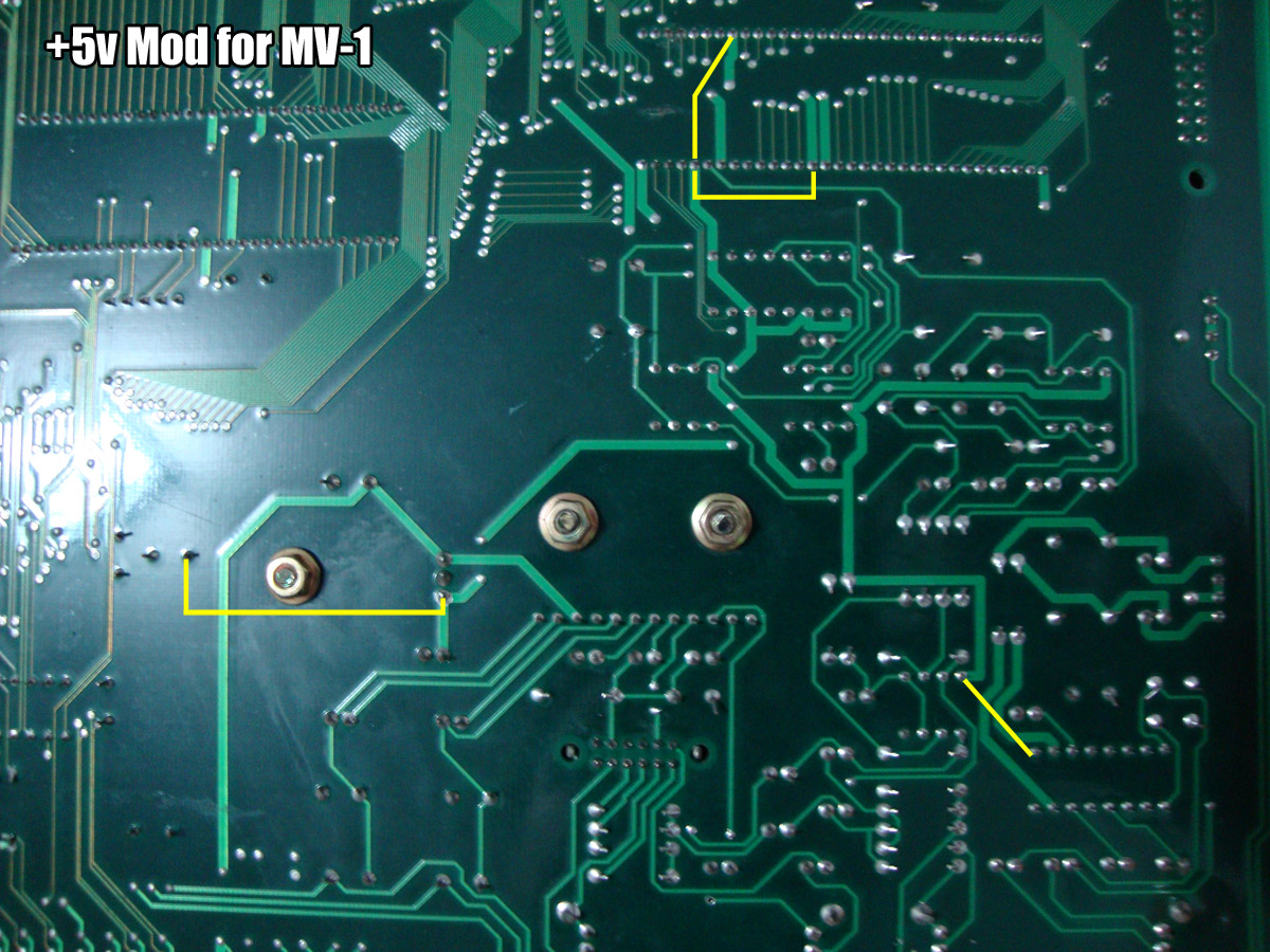
As shown in the picture above, just bridge any of the yellow connections to join the main and secondary +5v rails on the MV2.
Info provided by MKL
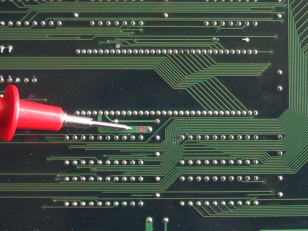 Locate the area in the picture and remove the solder mask to expose the copper.
 Now bridge the connections to complete the mod. This mod is only needed for the old MV4 mobo. The newer MV4F, MV4FT, MV4FT2 and MV4FS do not need the mod.
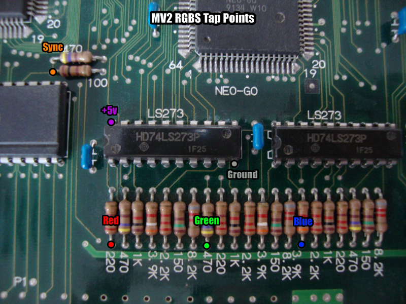
These are the Red, Green, Blue and Sync tap points on the MV2 mobo. They are the same physical locations as those on the MV2F.
This is the pinout for the 6116 SRAM on the MV1F mobo. If you are experiencing a Z80 error and have corrosion from a leaking battery check for continuity with these.
1 - SM1(5), Z80(37)
2 - SM1(6), Z80(36)
3 - SM1(7), Z80(35)
4 - SM1(8), NEO-D0(32), Z80(34)
5 - SM1(9), NEO-D0(31), Z80(33)
6 - SM1(10), NEO-D0(30), Z80(32)
7 - SM1(11), Z80(31)
8 - SM1(12), Z80(30)
9 - SM1(13), NEO-C1(74), Z80(14)
10 - SM1(14), NEO-C1(75), Z80(15)
11 - SM1(15), NEO-C1(76), Z80(12)
12 - GND
13 - SM1(17), NEO-C1(77), Z80(8)
14 - SM1(18), NEO-C1(80), Z80(7)
15 - SM1(19), NEO-C1(81), Z80(9)
16 - SM1(20), NEO-C1(82), Z80(10)
17 - SM1(21), NEO-C1(83), Z80(13)
18 - NEO-D0(12)
19 - SM1(23), Z80(40)
20 - SM1(2), NEO-D0(39)
21 - NEO-D0(40)
22 - SM1(26), Z80(39)
23 - SM1(27), Z80(38)
24 - VCC
This is the pinout for the SM1 IC on the MV1F mobo. If you are experiencing a Z80 error and have corrosion from a leaking battery check for continuity with these.
1 - VCC
2 - 6116(20), NEO-D0(39)
3 - Z80(5), NEO-D0(17)
4 - Z80(2), NEO-D0(14)
5 - 6116(1), Z80(37)
6 - 6116(2), Z80(36)
7 - 6116(3), Z80(35)
8 - 6116(4), Z80(34), NEO-D0(32)
9 - 6116(5), Z80(33), NEO-D0(31)
10 - 6116(6), Z80(32), NEO-D0(30)
11 - 6116(7), Z80(31), YM2610(61)
12 - 6116(8), Z80(30), YM2610(60)
13 - 6116(9), Z80(14), NEO-C1(74), YM2610(2)
14 - 6116(10), Z80(15), NEO-C1(75), YM2610(3)
15 - 6116(11), Z80(12), NEO-C1(76), YM2610(4)
16 - GND
17 - 6116(13), Z80(8), NEO-C1(77), YM2610(5)
18 - 6116(14), Z80(7), NEO-C1(80), YM2610(6)
19 - 6116(15), Z80(9), NEO-C1(81), YM2610(7)
20 - 6116(16), Z80(10), NEO-C1(82), YM2610(8)
21 - 6116(17), Z80(13), NEO-C1(83), YM2610(9)
22 - NC
23 - 6116(19), Z80(40)
24 - GND
25 - Z80(1), NEO-D0(13)
26 - 6116(22), Z80(39)
27 - 6116(23), Z80(38)
28 - Z80(3), NEO-D0(15)
29 - Z80(4), NEO-D0(16)
30 - VCC
31 - VCC
32 - VCC
This is the pinout for the Z80 on the MV1F mobo. If you are experiencing a Z80 error and have corrosion from a leaking battery check for continuity with these.
This is still a work in progress so it may not be fully complete.
1 - NEO-D0(13), SM1(25)
2 - NEO-D0(14), SM1(4)
3 - NEO-D0(15), SM1(28)
4 - NEO-D0(16), SM1(29)
5 - NEO-D0(17), SM1(3)
6 - LSPC2(101), AS04(13)E6
7 - 6116(14), NEO-C1(80), SM1(18), YM2610(6)
8 - 6116(13), NEO-C1(77), SM1(17), YM2610(5)
9 - 6116(15), NEO-C1(81), SM1(19), YM2610(7)
10 - 6116(16), NEO-C1(82), SM1(20), YM2610(8)
11 -
12 - 6116(11), NEO-C1(76), SM1(15), YM2610(4)
13 - 6116(17), NEO-C1(83), SM1(21), YM2610(9)
14 - 6116(9), NEO-C1(74), SM1(13), YM2610(2)
15 - 6116(10), NEO-C1(75), SM1(14), YM2610(3)
16 -
17 -
18 -
19 -
20 -
21 -
22 -
23 -
24 -
25 -
26 -
27 -
28 -
29 -
30 - 6116(8), SM1(12), YM2610(60)
31 - 6116(7), SM1(11), YM2610(61)
32 - 6116(6), SM1(10), NEO-D0(30)
33 - 6116(5), SM1(9), NEO-D0(31)
34 - 6116(4), SM1(8), NEO-D0(32)
35 - 6116(3), SM1(7)
36 - 6116(2), SM1(6)
37 - 6116(1), SM1(5)
38 - 6116(23), SM1(27)
39 - 6116(22), SM1(26)
40 - 6116(19), SM1(23)
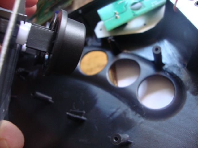
First, you need to remove the 4 rubber feet from the bottom of the console. There will be 4 screws under those feet. Remove all 5 screws.
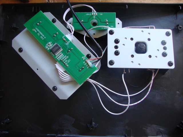 This is what you will see once the unit is open.
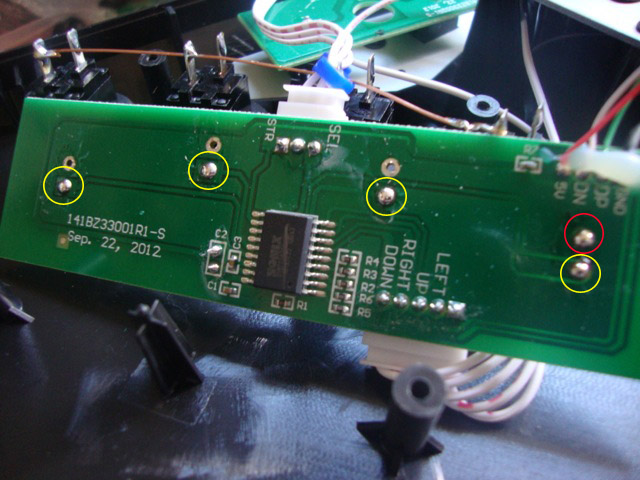
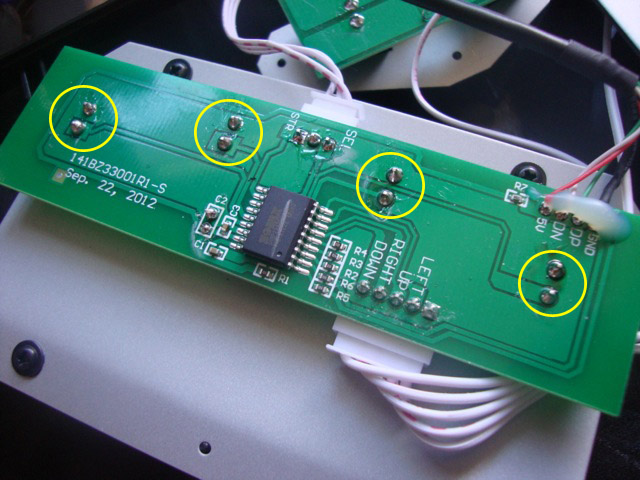 Now you will need to desolder these 8 points.
 Once you desolder all 8 points then you can move on to the next step.
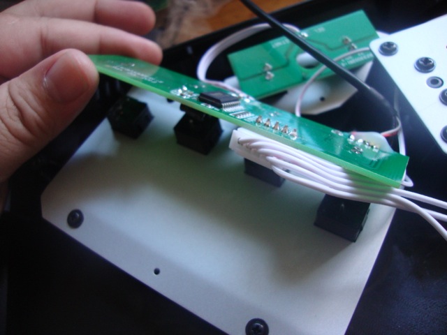 Gently lift the board up to access the button board.
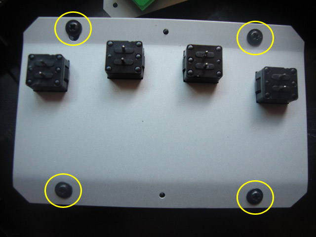 Remove the 4 screws.
 once you remove the 4 screws it should lift off very easily.
 You can save this for use in an old Neo Geo stick if you want.
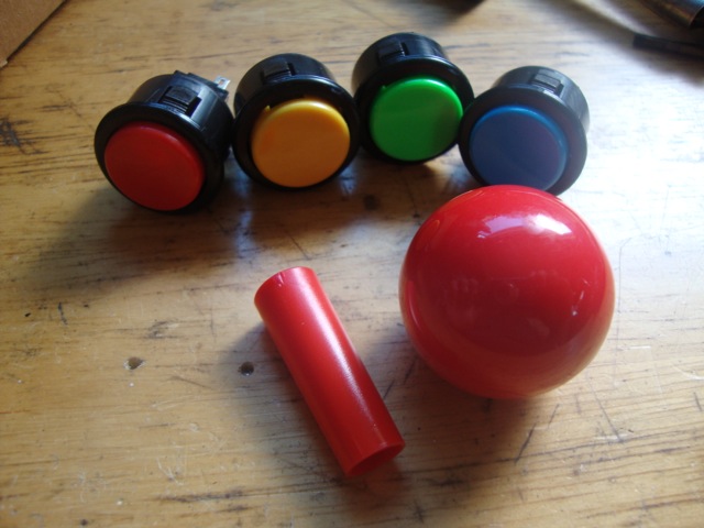 These are the parts you need, 4 x 24mm Sanwa or Seimitsu buttons I use snap ins, 1 x 35mm Ball top and 1 x Red LS Shaft cover. I get these parts from akihabarashop.jp.
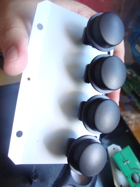
 Now push the buttons in to the housing. Make sure your colors are correct. Red is A, Yellow is B, Green is C and Blue is D. Make sure the snap in tab is locked in place like in the picture. If it isn't then push it a little harder and it should set.
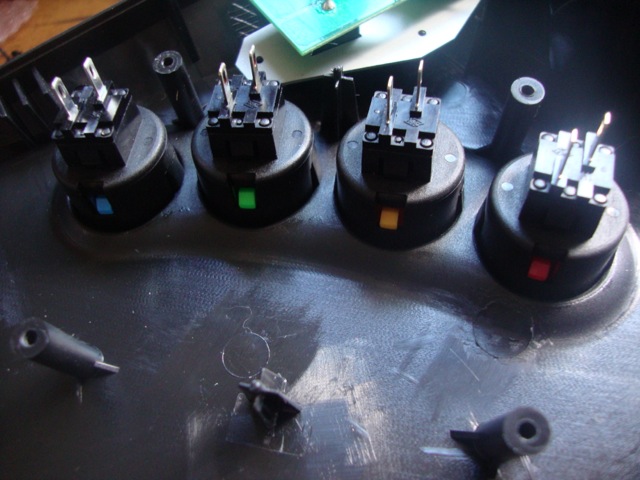 I put mine in like these. These are Seimitsu buttons and easier to work with since the tabs are staggered instead of parallel.
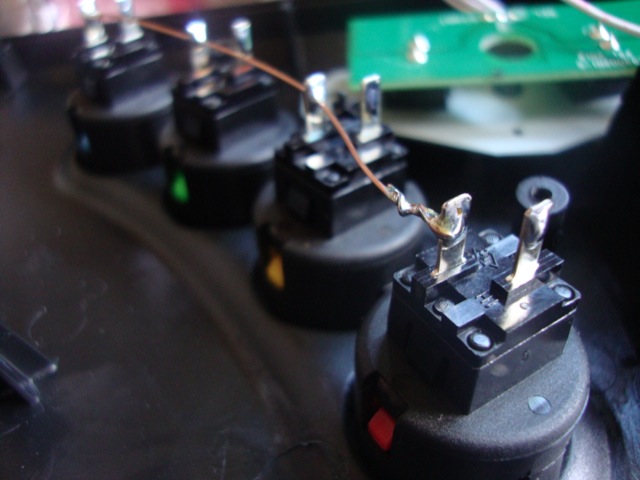 Next I use copper wire and connect all 4 buttons for the ground.
 Now fold the board over by the buttons like in the picture. And add solder to the points indicated.
 I use a zip tie to hold the board in place.
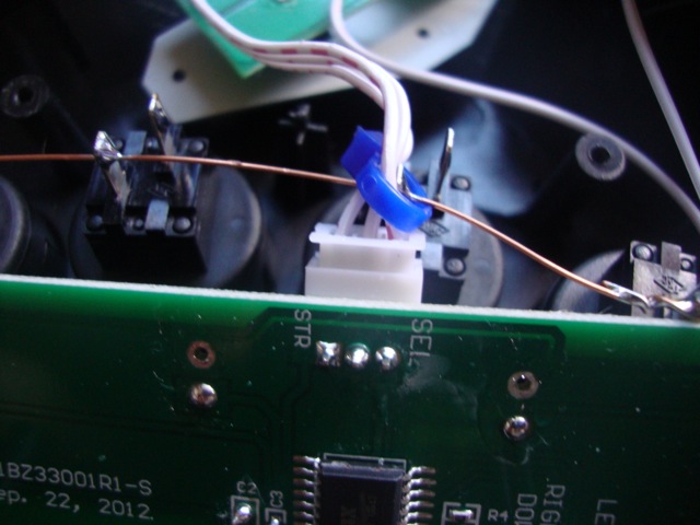
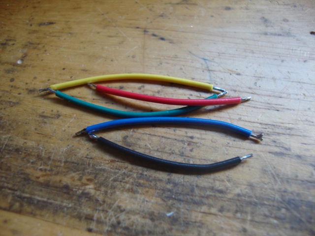 Now cut 5 pieces of wire, one for each of the 4 buttons plus 1 for ground. Since the ground for the buttons are all connected together you only need one connection for ground instead of another 4.
 Connect the ground wire tab to the board like shown.
 The connect the opposite tab to the A button solder point like shown.
 Repeat for the other buttons.
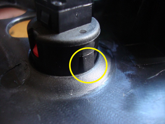
 Now for the stick, unfortunately Tommo wasn't very consistent with the way they made the sticks. Some sticks you can easily remove the ball top while others you will need to remove the entire joystick shaft and replace it. Use a flat head screwdriver and stick it into the slot on the bottom of the shaft. Then twist the ball top counter clock-wise. If you are using a good amount of force and it isn't coming off then you need to remove the entire shaft.
 In this pic you can see how the slot on the shaft got messed up, this is because this stick had a ball top that was glued on. The last 4 sticks I modded were all just screwed on. I'll make a seperate tutorial on how to remove the joystick shaft.
Before installing the ball top we need to install the shaft cover. You will need to trim the shaft cover about 1/4".
Once it's been trimmed then place it on the joystick shaft. Make sure you put the wider end at the top of the stick.
All you need to do now is just screw the 35mm ball top on. Do it hand tight then use a flat head screwdriver and place it in the slot on the bottom of the stick like shown earlier and then twist the ball top with your other hand to make it tighter.
That's all there is. You can finish the job by using better feet for the stick. We carry them in the store.
--Courtesy of NeoTurfMasta--
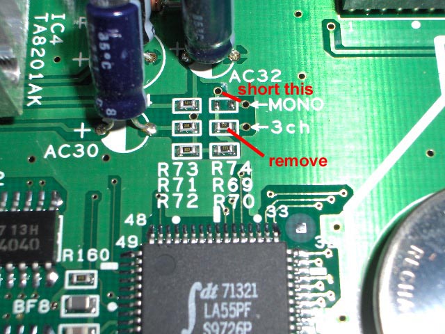
Remove the 3ch resistor and short the MONO connection. I took a piece of a resistors long leg and stuck it in the holes. Fit snug and its easy to remove if you ever change your mind.
If you do change your mind, just short the 3ch space and its back to normal. Now, I dont know the long term effect of this, I just did it this afternoon.
I seriously doubt any damage would occur to your board, game or cab. That is, as long as you can remove the resistor without jacking up your hyper board. But do it at your own risk.
The one flaw is you cant adjust the volume level. BUT the volume it does give out is just right for me on my Candy. Not too loud and not too soft. Two flaws if you consider you are losing stereo sound. If you are connecting it to a pure jamma cab, then its mono to begin with.
--Courtesy of NeoTurfMasta--
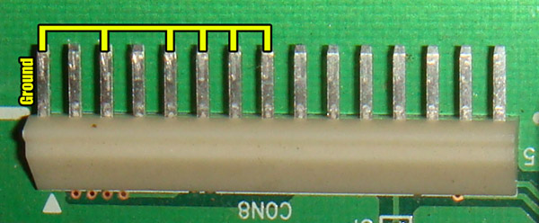
When playing a Hyper 64 driving game without the network link board you will need to ground pins 3, 5, 6, 7 and 8 on the 15 pin connector. Pin 1 is ground so you can solder jumpers from it as well. Grounding these pins tricks the CPU into thinking it is Machine #1 in the network lineup. If you do not do this the machine will just hang on the "Connecting to Network" screen.
--Courtesy of NeoTurfMasta--
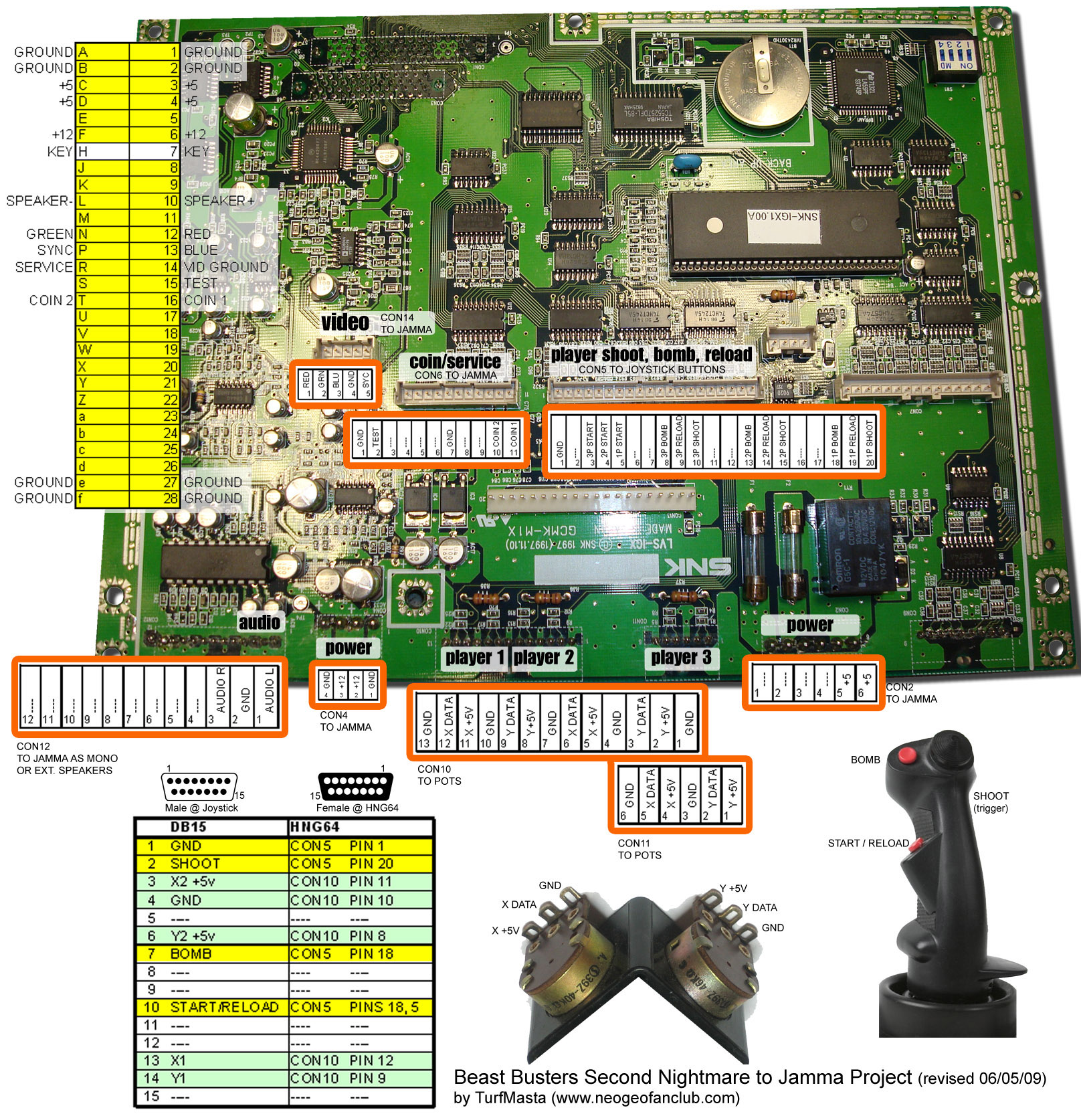
Beast Busters Second Nightmare to Jamma mod
(revised (06/05/09 by TurfMasta)
My rig requires you to bypass the large Molex connectors that are present and just cut the existing wires. When I did this several years ago, I could never find the proper adapters required to connect with the existing Molex-ish connectors. Probably would cost more than its worth, so next best thing is to just bypass them completely. If you are lucky enough to get a hold of the proper connectors, then head to CrazyKong.com and download my scanned BBSN manual. Its not a bad idea to download the manual and use it to accompany this document. Anything marked with a "----" under the pinout is just to show that these are not required to be cut or used in this mod. In other words, just leave them alone. This mod really should only be done by people with supergun or general arcade wiring experience. The only thing here that should be a little unusual for you is the analog part, but that's really it. Don't blame me if you break your precious BBSN board, I offer no guarantee on the accuracy of these instructions. If I do see a error I will update this document and photo accordingly. I have done this exact mod on two BBSN boards without any problems.
The "mod" is made up of really 3 different parts, building the Jamma interface, rigging an analog joystick, and making the joystick interface on the motherboard. I used a common Thrustmaster TopGun joystick mainly because I had one laying around. Any analog joystick will work, no digital joysticks will be compatible. "Why don't you use a light gun?" Because like most cabinet mounted gun games, the gun isn't optical at all and gets its X/Y location via the potentiometers(pots) inside.
First thing to do is get the Jamma edge connector built. Should be fairly straight forward, connect the appropriate signals from the "TO JAMMA" labels to your fingerboard. You may want to pull additional grounds from the motherboard to the fingerboard, and remember to always use a heavier gauge wire on the +5V and +12V lines. You should be able to just trace and cut the existing +5V wire from CON2 and solder the wire directly to the fingerboard. To save time, you don't HAVE to wire the Coin Credit parts since you'll probably prefer to set the game to Free Play.
If you don't have an old analog PC joystick laying around, they are easily found at thrift stores or resale PC stores. Steer clear from USB joysticks, as it has more brains inside than you need. Stick with an old DB15 stick and you'll be fine. Just make sure you get one that has enough buttons to support Fire, Bomb and Reload. The TopGun has 4 usable buttons, and I just removed the 4way hat completely. One good thing is, you should be able to use the existing wires and DB15 connector from the joystick and just re-wire them to the appropriate pinouts shown. On mine, I combined Start and Reload to one button.
Wiring the motherboard to a female DB15 is where things can get a bit difficult. With the exception of the analog connections, all the other pins should already have wires attached where you can cut and solder them directly to the DB15. Take note that the the pin numbers change direction and are not always sequential from right to left or vice versa. Player 1 analog controls start at 13 through 8 on CON10, with the sequence repeated on Player 2 and 3. Always start with wiring up just one joystick and testing it before taking on the task of all 3. At first you will need to set the game to just 1 player only so you can successfully calibrate the joystick. If you try to calibrate the controller and have it set to more players than you have joysticks, you wont be able to complete the calibration process and your calibration settings will not be saved.
That should be about it. Take your time with it and test the board after every completed part. Have fun killing zombies and check YouTube for the entire walkthrough of BBSN at My Youtube Page
-TurfMasta
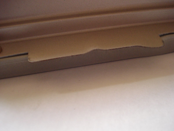
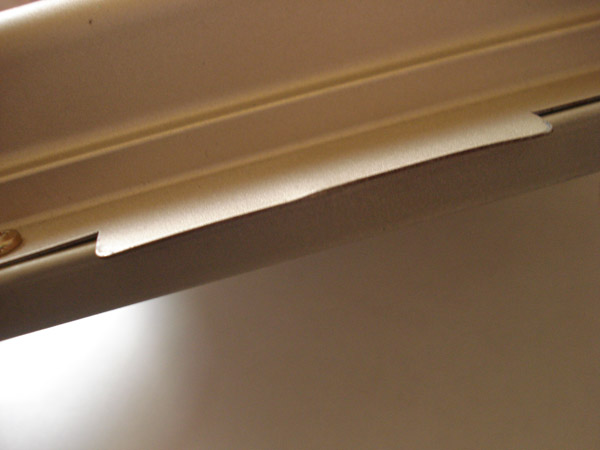
Sometimes I have found that if a game is not working at all and is known to be a working game it's usually because it's not making good contact with the board. Above is s bent fin on the hyper 64 cart. Since it's not flat it holds the cart up and prevents it from seating properly. These fins are made of a harder metal than it looks so bending it back can be done by simply hitting the cart shell against the a wooden table. I of course removed the insides before doing so.
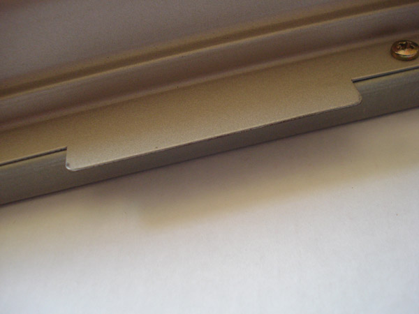
Above is how flat it's supposed to be. And below is how flat I got it. After that the game booted right up with no problems.
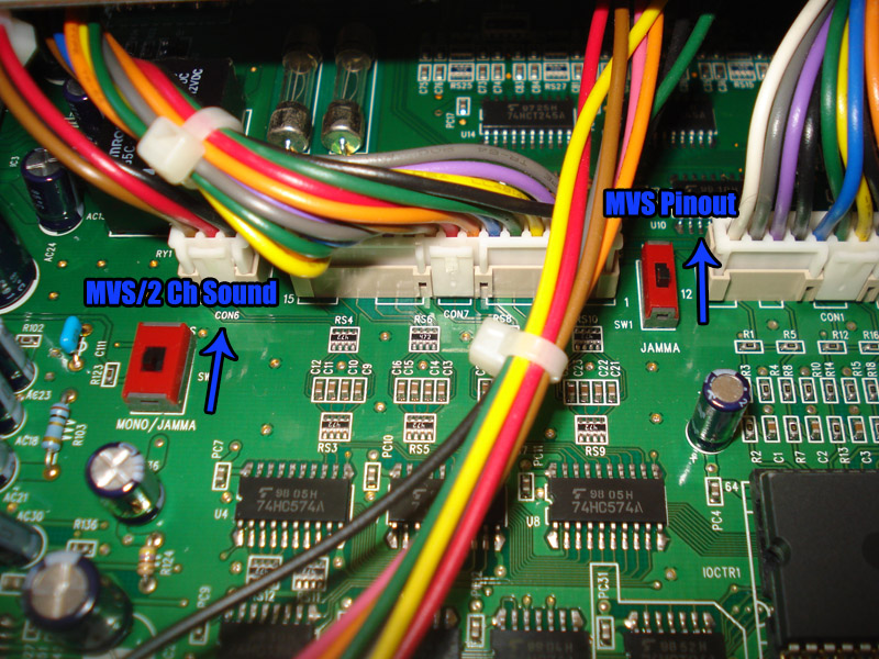
When installing a Rev 2 Hyper board into an MVS cab make sure you flip SW1 and SW3 to MVS. Doing so makes the Rev 2 have an MVS pinout along with MVS sound output. If you forget to flip SW3 to MVS then the board will only output mono sound.
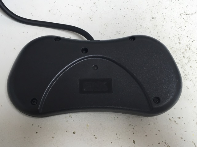
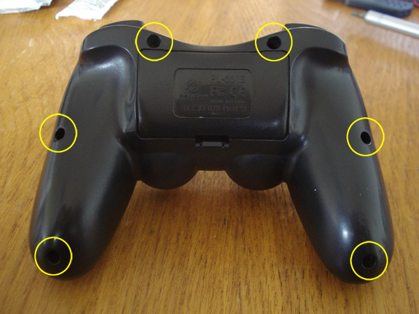
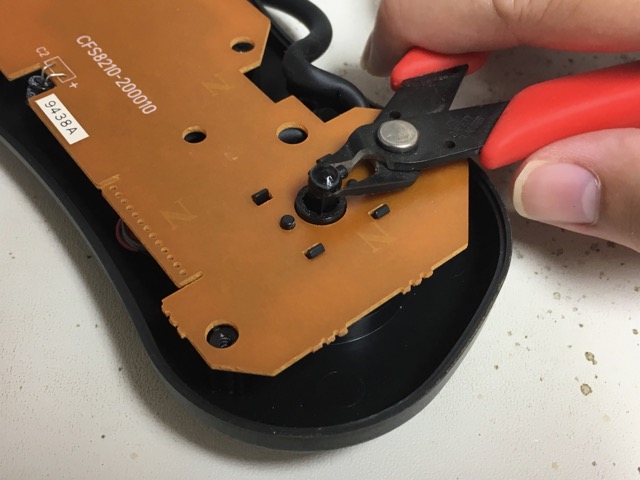
First remove all 5 screws on the bottom of the joypad.
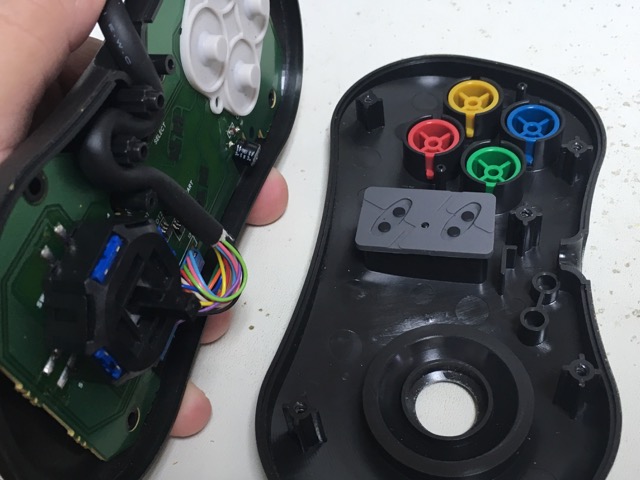
Once open, Using a pair of wire cutters(for grip) pry the thumbstick out. This will easily remove the thumb pad on the opposite side.
Like so.
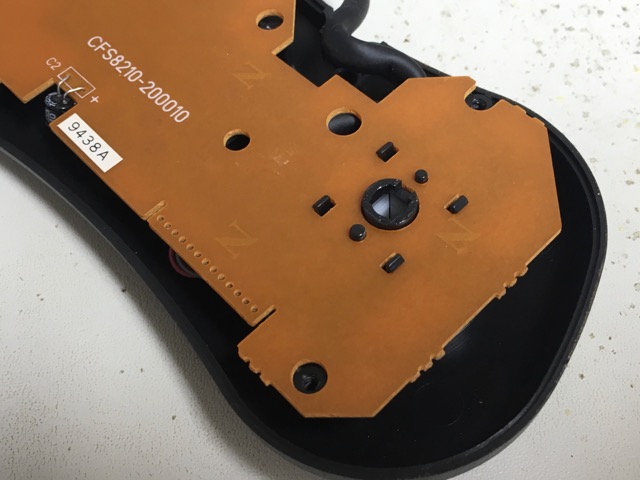
It should now look like this.
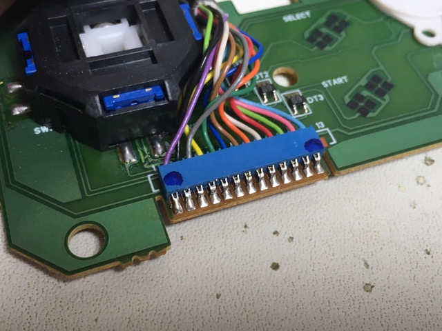
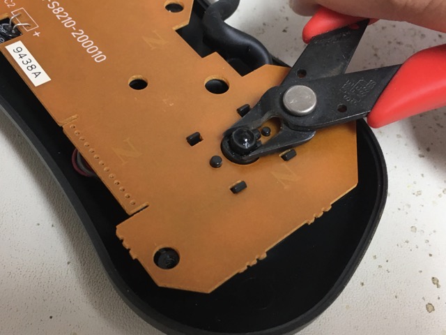
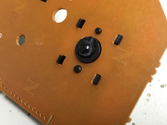
Now remove the PCB from the housing, locate the dark blue wire which should be the pin 6 from the left side of the harness.
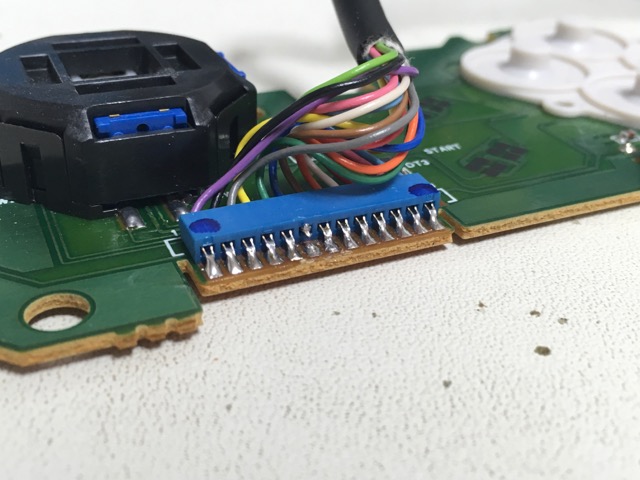
Now cut the metal tab connecting it to the PCB or you can just cut the dark blue wire, your choice.
Now slide the thumbstick back into it's place. Make sure the small tab on the thumbstick is pointing up.
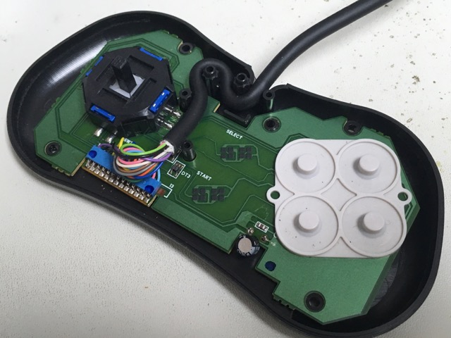
Now place the PCB, back in the bottom half of the housing and route the cord like shown in the picture around the retaining posts.
Leaving the top of the controller on a flat surface or flat in your hand, place the bottom half back onto the front half.
It should look like this now.
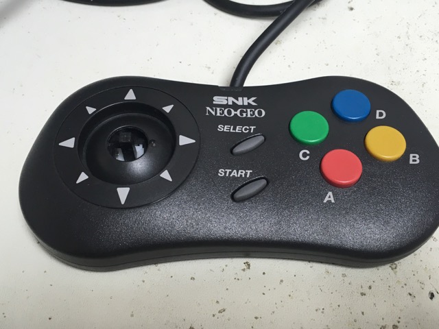
Put the thumbstick back on, make sure the dot is facing up. Then flip it over and put the 5 screws back in.
And that's it. You can skip popping off the thumbstick if you can cut the dark blue wire from the back, just be careful.
In this tutorial you will be using the stock square gate to create an octo gate for 8 way heaven.
Pull off moves even easier than before and squash your opponent.
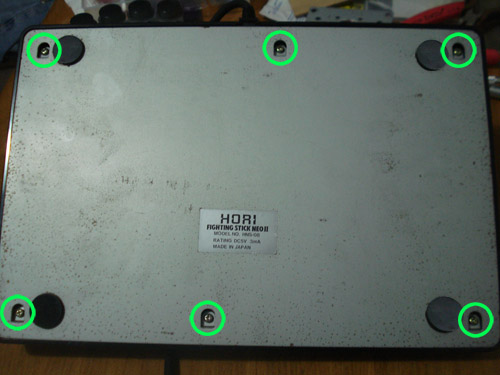
First you need to open your Neo Hori stick. Remove the 6 screws on the bottom
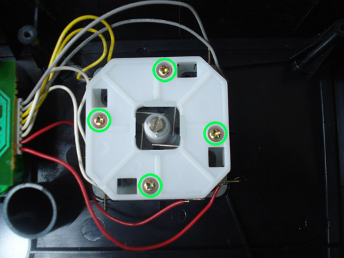
Once open, remove the 4 screws that hold the square gate down.
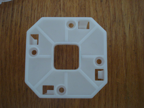
You may have to push on your stick to pop out the square gate. Do it right and you will have this.
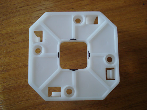
Now using a sharpie mark off the other 4 corners. Use the lines on the plastic as guides. Your triangles will only be 1mm in height and about 2mm wide.
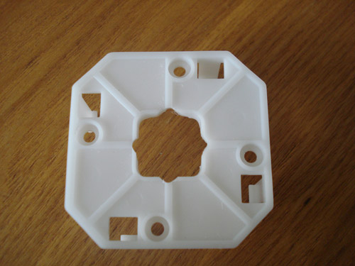
Now using a Dremel or similar tool cut away at the triangle marks you made. Make sure you cut the height of the plastic. Do not cut past the plastic rib. Only cut 1mm inward.
Now put the gate back onto the joystick assembly and screw on your bottom plate. Now you will have even more fun with your Neo fighters.
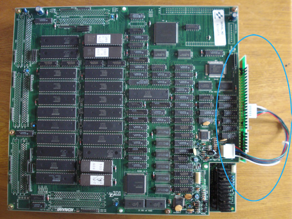
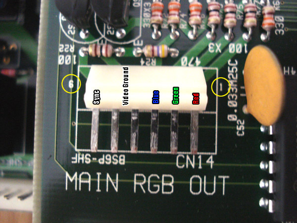
In this tutorial you will be hacking your Konami GX PCB to operate without the additional sub PCB. Using the GX without the sub PCB results in a non-colored and non-rendered picture usually a weird shadowy picture. This is because the GX generates the RGB on the daughter board but has the jamma edge on the main board. The sub PCB connects to the main board and plugs into the RGB output on the daughterboard. In the above picture is the sub PCB attached to the main board.
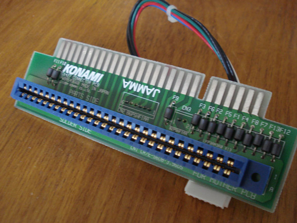
This is the sub PCB, notice that everything is almost a complete pass-through except for the video lines.
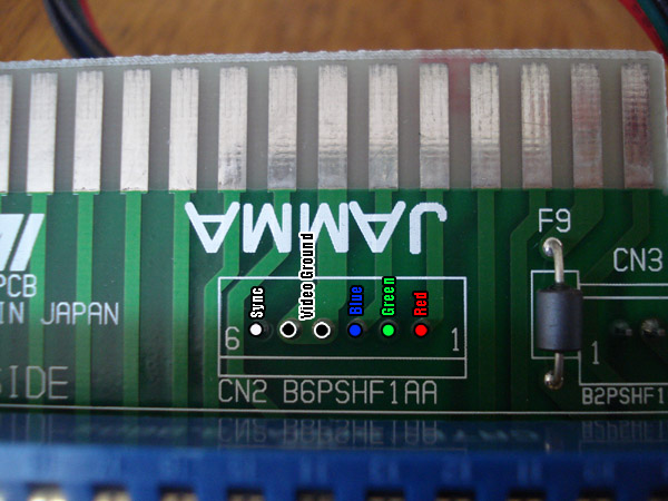
This is a close up shot of the sub PCB video section. The connector plugs in on the opposite side. R,G,B and Sync all have 1 line each but Video ground has 2. Remember the pinout from 1-6.
This is the bottom of the main board right beind the jamma edge. These are the places that you will be making a connection to for the RGB lines. You can of course solder to the jamma edge instead if you prefer.
In this pic the yellow circles indicate which connectors we would be soldering to make the connection. On the other side of those yellow circles are ferite beads. Now you can either desolder them completely then solder to the points for RGB as indicated previously or you can cut the 3 traces in the blue area. I chose to cut them since the board never uses them anyway. Your main RGB comes from the daughterboard as well as 2nd monitor RGB. Nothing is needed from these 3 traces.
Here you can see I used 28awg wire aka ribbon cable to solder to the points needed. RGB and Sync as indicated previously. For video ground I just take it from the main ground since the original video ground doesn't have any additional filtering, it's just a ground.
Here are the 3 trace cuts. Keep in mind that if you don't cut these 3 traces your RGB will look like composite video, blurry. You will also need to cut the trace above the sync point. If you don't cut this trace you may experience sync issues, if you have a sync cleaner then this step is not needed. When cutting traces like this I use my Dremel, you can also use a regular xacto knife or blade. Just make sure there is a nice gap in the traces.
This is the connector on the daughterboard. This shows the pinout for it as well. Keep in mind you will be soldering to the back of it so the pinout will be reversed.
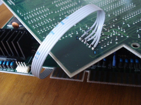
This is the underside of the connector on the daughterboard. I usually mark my wire as to which is pin 1 with a small black mark. Now this is just the way I soldered to the board. If you prefer you can solder directly to the pins but I like to keep it clean. That's it, now go ahead and put the board back together. Make sure the connectors are mated good and then play you newly modded GX.
Neobitz Vs. JROK
A lot of people ask me which encoder is best to use. Truth is neither are the best as a whole. After building several CMVS and Supergun units I noticed the difference and will share them with you.
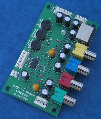
The JROK encoder. The JROK has amazing compatibility with it's Composite/S-Video circuit, providing a well balanced color saturation and clarity to it's picture. The JROK is recommended for most Supergun applications. But the JROK Component circuit is inferior to the Neobitz's Component circuit. The JROK Component circuit has very high color saturation making the picture disappointing to some and over saturated.
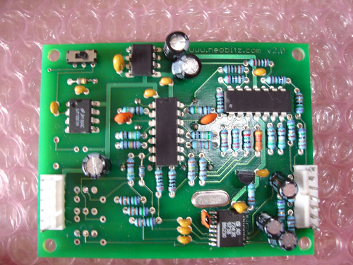
The Neobitz encoder. The Neobitz has amazing compatibility and picture perfection with it's Component circuit, providing a well balanced picture with clarity. The Neobitz is highly recommended for Neo Geo applications as it offers the best picture compared to the JROK. However the Neobitz Composite/S-video circuit can play many JAMMA games but has compatibility issues with a bunch of boards.
Overall the best picture I have experienced on a Supergun was using a combination of a Neobitz Component circuit with a JROK Sync Cleaner. Of course if you are looking to build a Supergun and only plan to use S-video/Composite then the JROK would be best for you. Again this my personal preference only.
One thing to remember also is that the JROK and Neobitz do NOT alter Sync refresh rates. If you are having problems with the picture displaying correctly on your TV as far as positioning or rolling it is purely the game board.
The awesomeness of a battery leaking all over your beloved arcade board. Can life get any better? I submit that it can not. This tutorial is for PGM cart boards only. I know this pic is from a cave board. Sorry. Send me a pic of a leaking cart board battery.
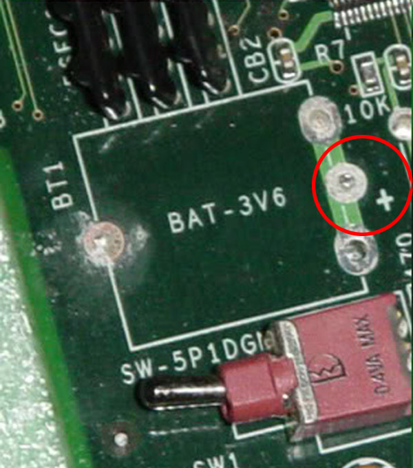
First thing to do is to remove the battery. Desolder or snip, choose your weapon. Either way you still need a soldering iron. Keep note of where the + sign is for when you install the socket. The PGM has more than 1 board type so layouts may differ so adjust your mod accordingly.
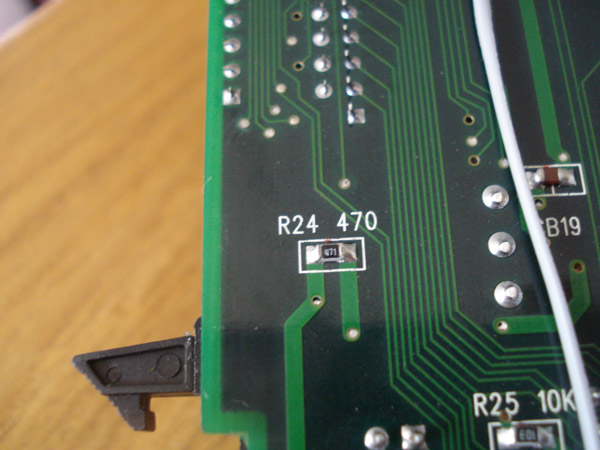
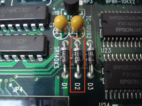
Now you will need to remove both the 470ohm resistor marked R24 and the D2 diode. R24 is on the bottom of the board and D2 is on the top of the board. Both are in the same area.
On the mobo I am doing the mod on the toggle switch was close to the edge. You will need to cut out this section of the battery holder to make room for the toggle switch as it is close to the battery. I am using a 20mm coincell battery holder and a CR2032 battery. Once you've cut it go ahead and attach it to the board. Make sure the positive terminal(top) goes to the + sign on the board.
This is how it looks installed. And that's it. Now you don't have to worry about difficult battery swaps or the battery leaking onto the mobo. Coin cells don't leak very often but can if you store your boards in a hot place just like any other battery. Make sure you store your boards in an area that won't get hotter than 90 degrees or in direct sunlight.
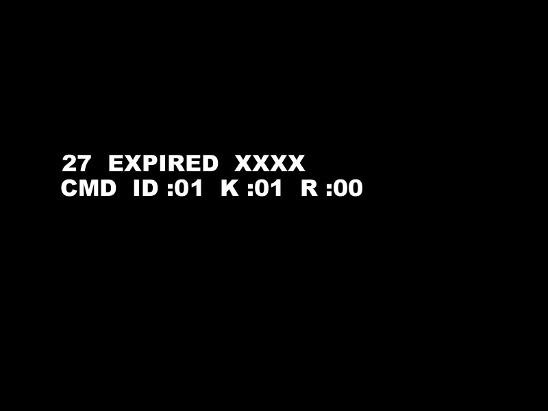
Have you ever gotten the above error trying to play your PGM games? This is a hardware related problem. It happens when the clock signal for the ASIC chip in the game cart isn't getting a good signal.
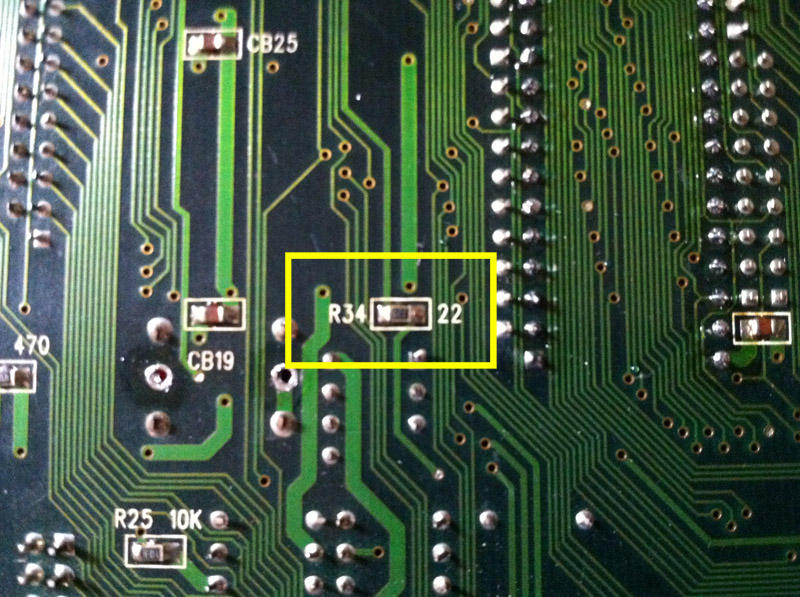
The error occurs when R34 starts to go bad. R34 is rated at 22ohms, if your board is giving the error, check the resistance of this resistor. If it is different from 22ohms +- X% then it might be the problem.
I do not know how off the reading can be and still function correctly as mine was reading at 330ohms so my system could not boot any games. This resistor is a surface mount one so make sure you know how to desolder it correctly.
Above is a pic of the osciallator that spits out the clock frequency. It provides the clock signals for both the 68k on the mobo and the ASIC chip in the cart. These two processors need to be on the same frequency to operate correctly. Pin 3 of the oscillator goes to both processors via a 22ohm resistor for each processor.
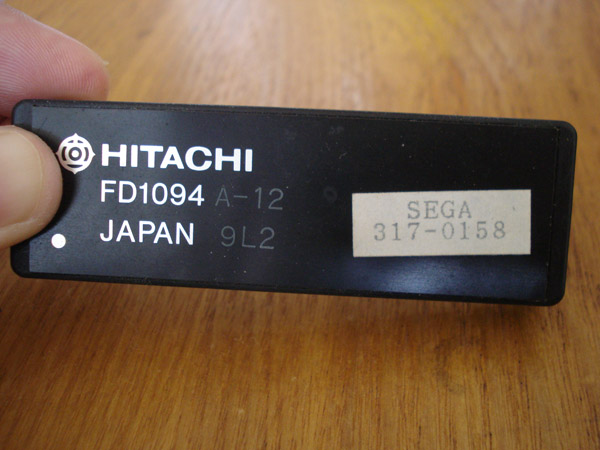
This is the basic enclosed CPU on a Sega Suicide board. This particular one is from a Moonwalker PCB. Despite what others may claim, there is no way to revive a Moonwalker PCB after the battery in the CPU dies. There is no evidence that anyone has sucessfuly revived a Moonwalker board.
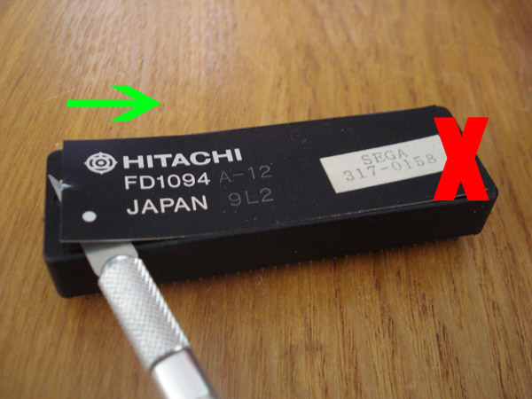
Using an exacto knife simply insert it on the LEFT side of the CPU. If you insert it on the right side you risk accidentally disconnecting the battery. Once you get the lid open slightly, you can then peel the lid over to the right side. Be gentle and do not go too fast as there is a wire in the lid. Once open you will see a leaded CR2032 battery.
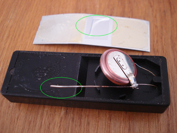
Nothing happens if this wire is removed. I believe it was put there to booby trap a battery swap effort. If you pull too hard it causes the battery to disconnect which results in a dead CPU.
Once open, you can see marking indicating which wire is which.
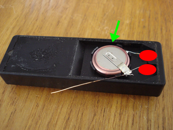
Now you will need to push the battery back in it's holder. After doing so put 2 dabs of hot glue in the red spots, this is to hold the leads down. If you do not do this booby trap number 2 kicks in when you try to add the new battery. Booby trap number 2 is that these leads are stiff enough to be spring loaded, once you place your soldering iron on the lead it springs out and breaks the connection to the battery. With the hot glue in place it holds the leads from doing so.
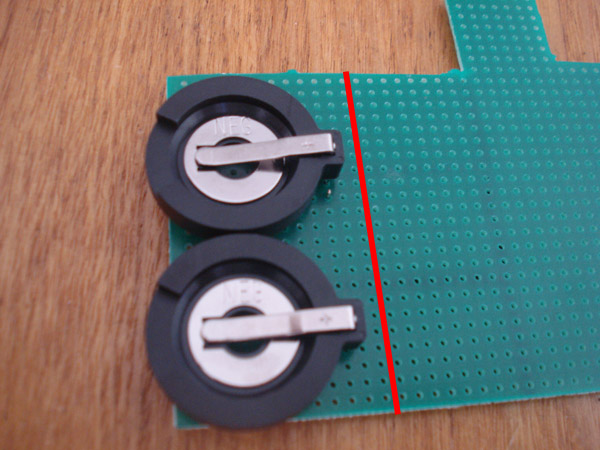
Now using 2 coincell battery holders, mount them to a black perfboard. You might need to drill the holes bigger so the leads fit through. These battery holders are 20mm PCB mount type. The red line just indicates that you only need a PCB that big. The perfboard I am using for this tutorial is intended for something else so don't pay attention to the size of it and the markings on it.
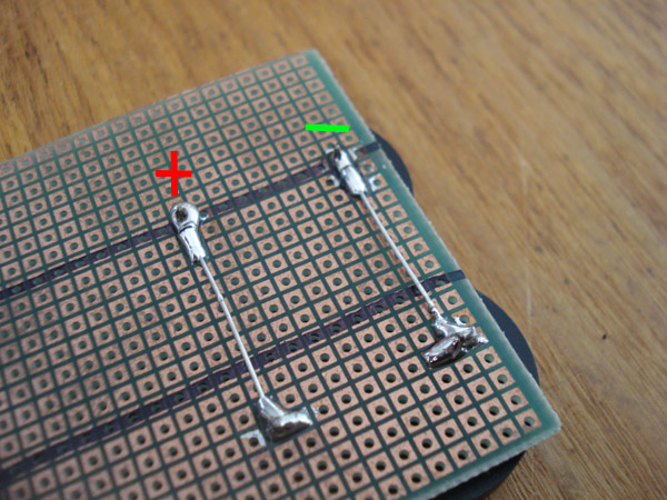
On the solder side of the perfboard you will need to join the leads in parallel, positive to positive and minus to minus. I used resistor legs that were cut off to joint them.
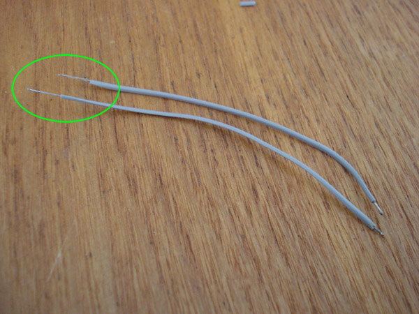
Now you will need wire that is about 3" long. I am using 28awg, notice that one side is tinned with short leads and the opposite ends are un-tinned and longer. The longer ends will be attached to the battery leads on the CPU.
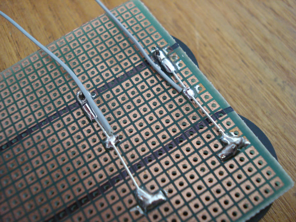
Take the shorter ends of the wires and solder them to the leads on the new battery board. One for positive and one for minus.
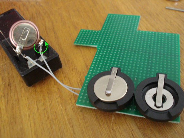
Now take the longer side of the wire and WRAP them around the correct wire lead nice and tight where there is no play. Positive to positive and minus to minus. Now solder them to the leads.
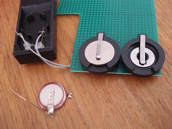
Once the wires are soldered in you can then remove the old battery. MAKE SURE you have your new battery in one of the sockets before removing the old battery.
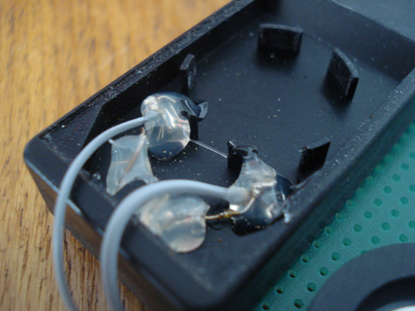
Once you have removed the old battery go ahead and apply some hot glue to the ends so they stay down and not move.
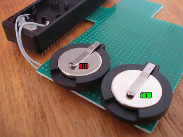
Since the swap is already done, this is how you swap in a new battery down the road. Since you have 2 sockets connected to the CPU in parallel you can have batteries in both sockets at the same time. In parallel it will still be 3V, if the batteries were in series meaning positive to minus and positive to minus it would be 6V. So when it's time for a battery change put the new battery in next to the old one.
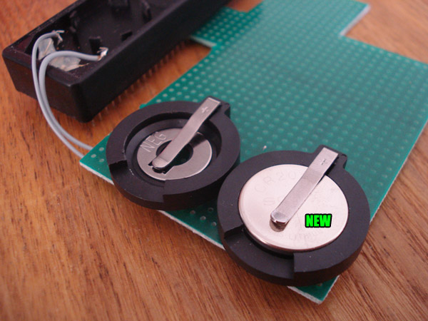
Then simply remove the old battery. These batteries usually last longer than 5 years but I would check the battery every 3 years just in case. Remember that heat will make a battery drain faster.
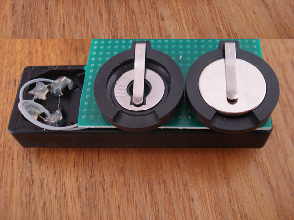
You can mount the PCB onto the CPU like so or any way you see fit. Just make sure it's secure and the leads are covered up under the board. You can use adhesive backed foam board to cover the underside of the battery board.
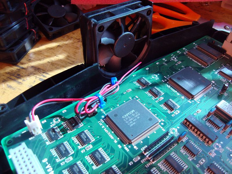
This is the installation guide for the CPS2 fans sold in the JNX store. First you will need to open your A board. You will need to remove the 4 Torx T20 screws. Then lift off the shell. Towards the back is the fan.
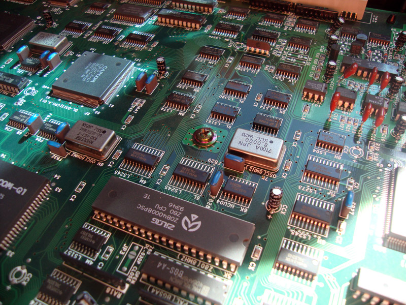
Next, remove the phillips screws in the center of the board.
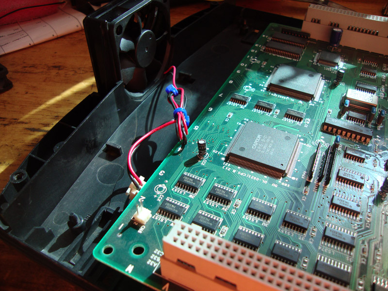
Now lift the board and pull it forward to reveal the fan wire guides.
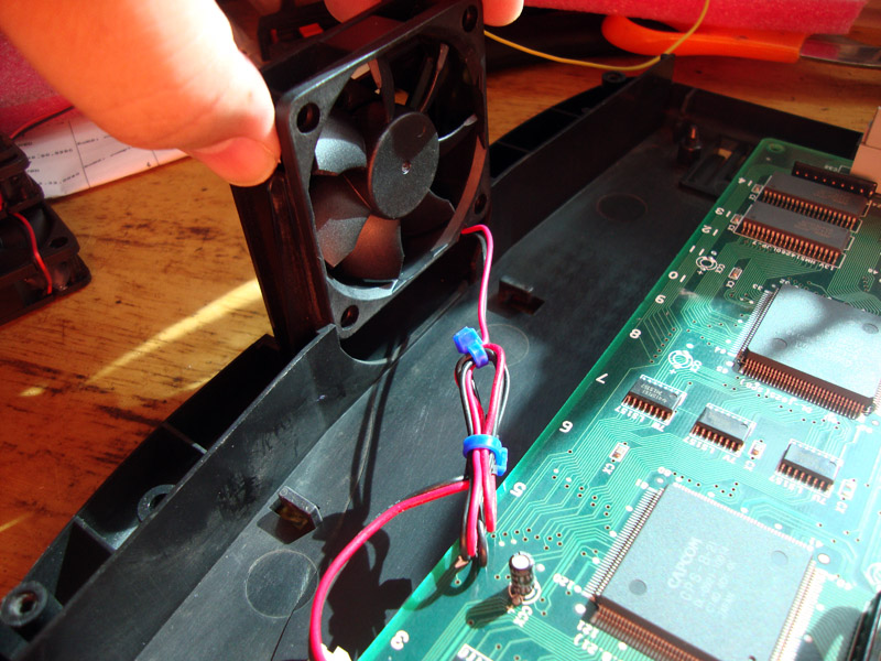
Now lift and remove the old fan and unplug it from the board.
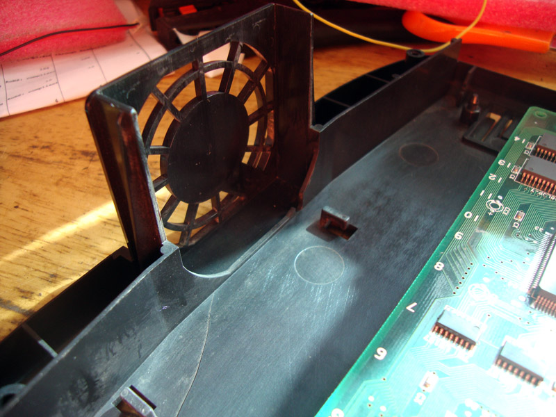
This is what you should be seeing.
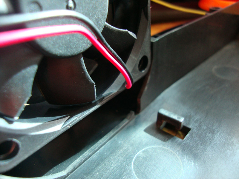
Now slide the new fan in with the label facing the outside of the board. Guide the fan all the way down, the wires might not line up with the notch but it isn't a problem.
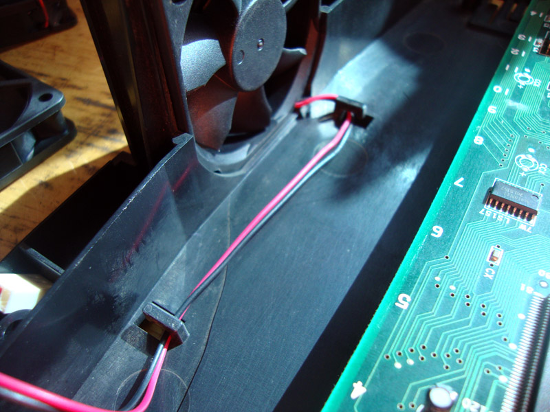
Run the fan wires under the guides as shown.
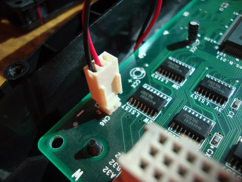
Place the board back on and tighten the phillips screw that was removed earlier. Plug in the connector as shown. You may want to zip tie any extra length on the wire.
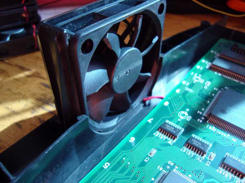
That's it. Now put the shell back on and play some CPS2 without having to listen to a jet plane taking off.
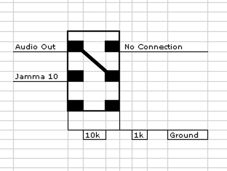
Adding this switch is as easy as pie. This is the solder side of a DPST(Double Pole-Single Throw ON-ON) switch. This is the same setup I use in all the Super Guns I have built.
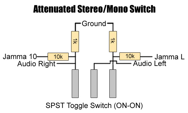
All you need is a SPST switch (Single Pole-Single Throw ON-ON) switch. This is the same setup I use when requested.
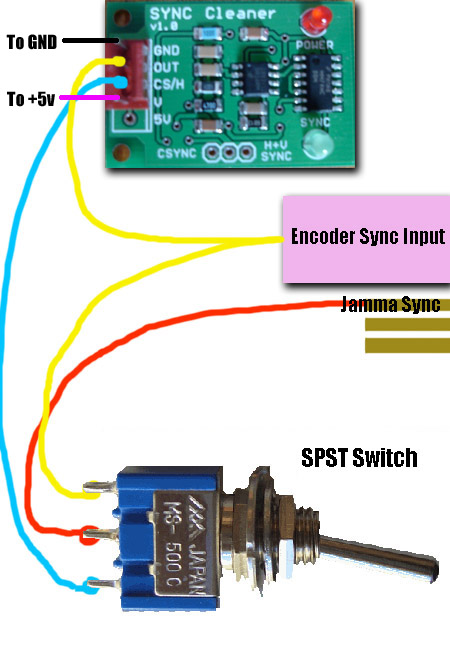
Adding this switch is as easy as pie. You need a Single Pole Single Throw switch (ON-ON) and a JROK Sync Cleaner. As you can see the sync from the jamma board goes to the middle pin, the Sync Cleaner INPUT goes to the bottom pin and the top pin goes to the encoder and hooked up to the sync cleaner OUTPUT as well. Doing it this way is easiest. This is the same setup I use in all the Super Guns I have built.
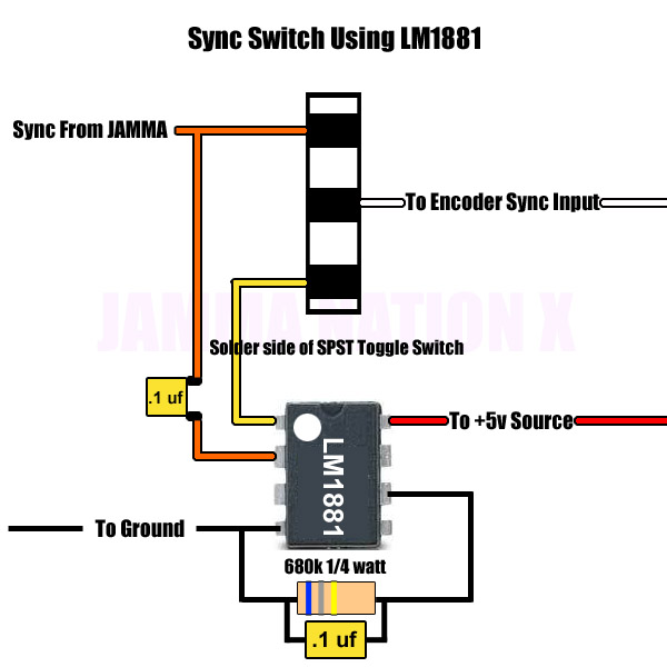
You will need the following parts:
1 x SPST (ON-ON) Toggle Switch
1 x LM1881 IC
1 x 680k 1/4 watt Resistor
2 x .1uf Capacitors
In the pic is the solder side of the SPST switch, the sync from Jamma goes to the top pin and also to the sync input on the LM1881, middle pin goes to the encoder's sync input and the bottom pin goes to the sync cleaner's output.
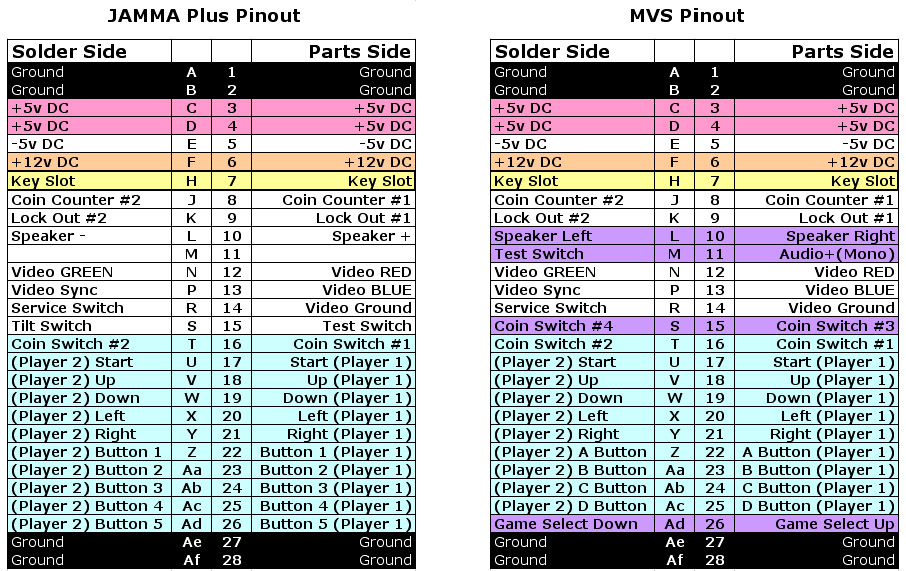
Above is the Jamma pinout as well as the MVS pinout. The sections in purple are the differences between the two.
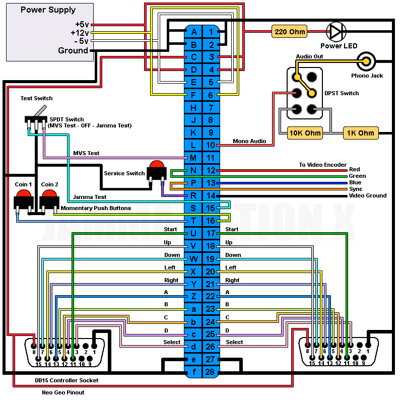
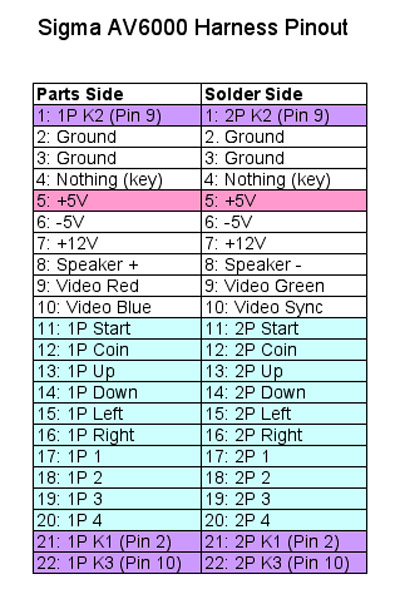
Above is the Sigma AV6000 pinout. The sections in purple are the wires that can be used for a kick harness. The Pin numbers on the purple sections correspond to the pin number on the controller ports. The Sigma uses the Neo Geo controller pinout with pins 2, 9 and 10 being extra.
This Pinout should work for AV6000, AV7000 and Raijin 44-pin Superguns.
Thanks to SuperDeadite for some of the pinout breakdown.
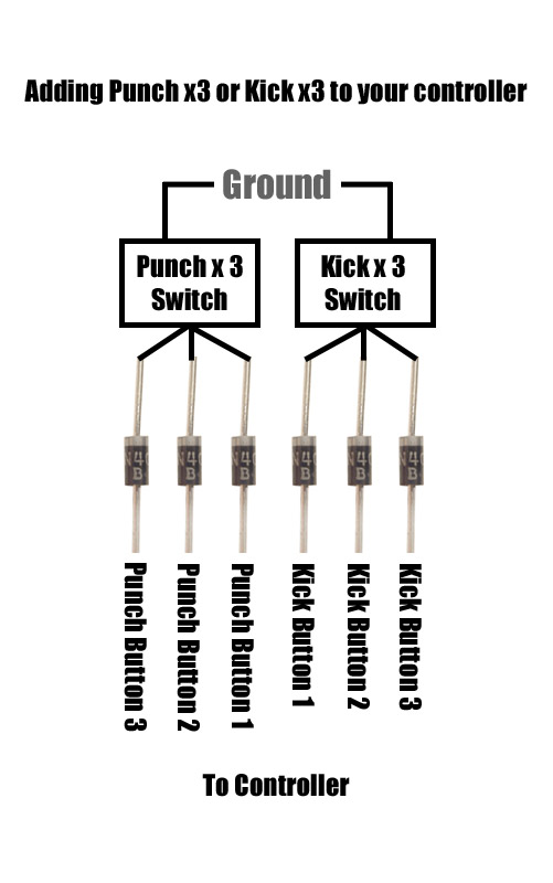
Above is the general idea behind an x3 function. There are many ways to do it but this is by far the simplest one to understand for most people. You will need some 5v diodes, the ones I use are rated 1 amp as I have a lot of them. There are 2 ends on the diode itself, you will notice that one side has a line on it, this is the direction that the diode flows in. The reason why you need the diode is so that when you push any of the buttons in the group it won't activate any other buttons. For example, you push punch 1 and it ends up triggering punch 2 and punch 3 as well.
Since the diode only flows in one direction it prevents this from happening. Follow the picture above to make these x3 functions. The 2 switches represent a button you will be using to activate the x3 function, most people use trigger buttons on their controller for the x3 buttons. As you know buttons have 2 pins, one pin goes to ground and the other the signal. If you wanted to add an x3 function to your trigger button, look at the button and you will see the 2 pins I'm talking about, simply add a wire to the signal pin and the other end of the wire goes to the 3 diodes that go to the other button signals.
If you have any questions feel free to ask.
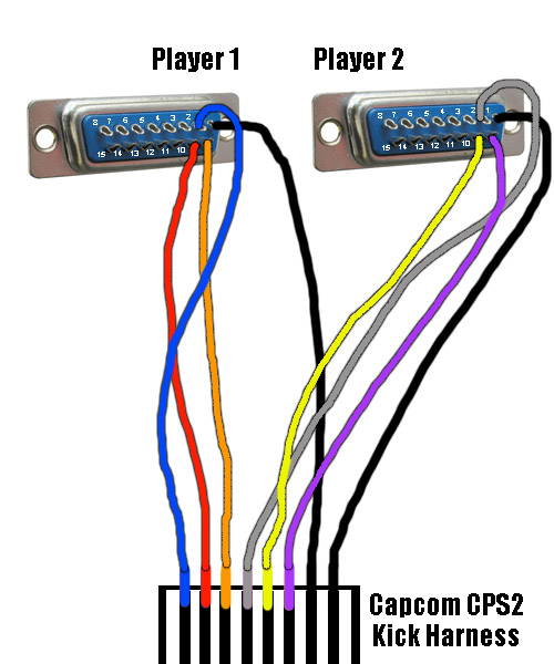
In the picture is both Player 1 and Player 2 controller ports. We are looking at the solder side. If you based your controller pinout on the epic Neo Geo pinout you will have 3 unused pins - 2, 9 and 10. Even though the Neo Geo pinout says pin 4 and 9 is D, 9 is used rarely and mostly only on mahjong games.
On the bottom of the picture is a fake CPS2 harness just to give you an idea of what you are doing. Please make sure you read the CPS2 kick harness pinout when actually doing this since wire colors can change. You are simply taking the wires from the kick harness and soldering them to the unused pins on your controller ports.
Please remember that you will need to have those pins in your controller connected to the buttons you want to assign them to.
So for example I want to connect the blue wire which is low kick for player 1. I solder the blue wire to pin 2 on the controller port and in my controller I connect pin 2 from my controller cable to my low kick button.
Repeat for the other 2 kicks for player 1 then don't forget to connect the ground which is the black wire. There are two of them one for each players controller, if you are using the Neo Geo pinout you connect the grounds to pin 1.
CPS2 Kick Harness Pinout:
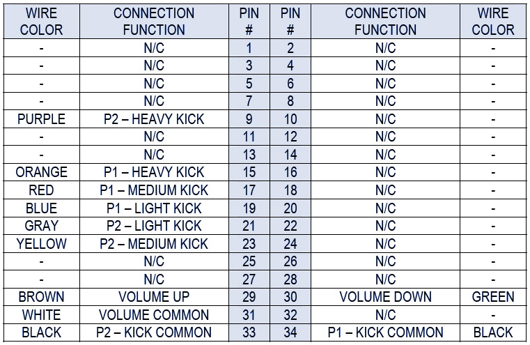
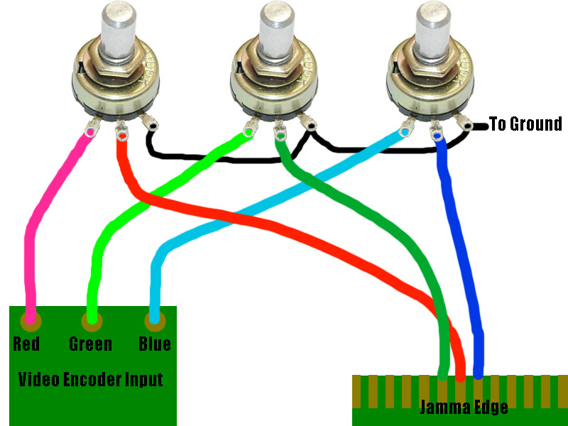
In the picture are 3 pots, the jamma edge and the video encoder RGB inputs. I use 500 ohm pots for all my RGB applications, some use 1K.
The picture couldn't be any clearer as to how you wire it up. Don't forget to connect the ground to the pots as seen above (Black Wire).
As you can see the ground wire connects to pin 3 of the pots. If you would like to change the direction you turn the knob to increase color brightness,
simply switch the wires of pin 1 and 3 on the pot so the ground is on pin 1 and the color output from the pot is on pin 3.
**Important note, if you have on-board pots it is best to remove them completely as even when fully open the pots add some resistance that may be unwanted.