Genesis 1 Mods
How to Add S-video to your Sega Genesis 1st Gen
In this guide you will learn how to add S-video output to your Genesis 1 using the internal CXA1145 Sony Encoder. Credit for the simplified circuit goes to viletim. Thanks dude.
Tools Needed:
Phillips Head Screwdriver
Wire Cutters
Soldering Iron
Solder
PC Board (Available at Radio Shack)
1 Panel/Chassis Mount S-video Jack, Can be bought here
1 Red Panel/Chassis Mount Phono Jack
1 White Panel/Chassis Mount Phono Jack
1 NTE85 Transistor (Or similar)
1 27ohm 1/4 watt Resistor
1 75ohm 1/4 watt Resistor
1 220uf Electrolytic Capacitor
Some Ribbon Cable or 28-30awg wire
Unibit (For Making Jack Holes)
Hot Glue Gun
Building the Luma Signal Amp
You will need to build an amp for Luma. The value of R1 for Luma is 27ohms. Keep in mind that some transistors have a different pinout so make sure you download your transistor's datasheet to verify it's pinout. The schematic is using an NTE85 transistor.
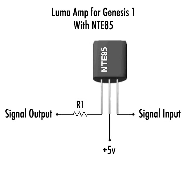
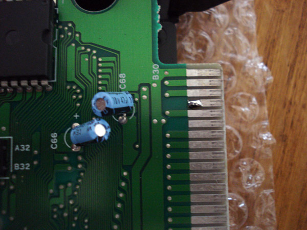
The picture above is for the NTE85 only. It's a pretty straight forward design, so you can't really mess it up. The Luma input is from Pin 16 on the Sony CXA1145 chip and Chroma is on Pin 15. You can either take the signals from the top side of the board which is a little harder since you have smaller area to work with or you can take it from the bottom side which is way easier. This circuit can be used on any CXA1145 equipped console including the Neo Geo AES.
For the Chroma output you simply need to connect the 220uf cap to pin 15 on the Sony chip. Connect the NEGATIVE leg to pin 15 and the POSITIVE leg to one end of the 75ohm resistor. The other end of the resistor is your Chroma output.
This is the best combo that I have used resulting in a nice bright picture with vivid color with significantly reduced color bleeding. In the original circuit design it was reccomended to use 33ohm for both outputs but this resulted in over-saturated color and bleeding.
Here are some screenshots from a Genesis with this S-video circuit comparing the old complicated S-video circuit vs the new:
6 in 1 Cart
Composite

Old S-video

New S-video

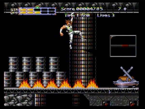
Strider 2: Strider Returns
Composite
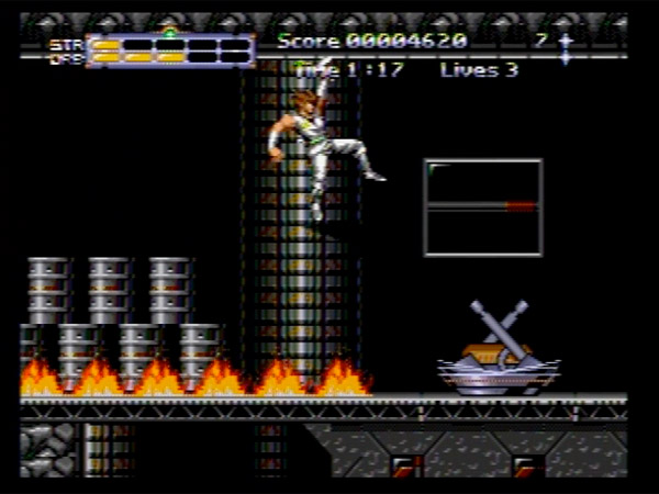
Old S-video
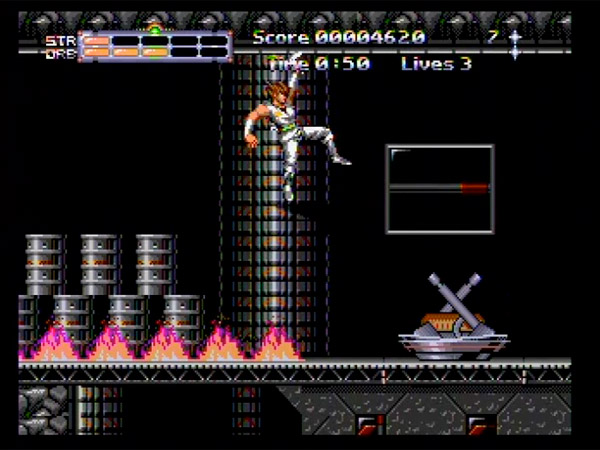
New S-video
Columns
Old S-video

New S-video

Neo Geo S-Video
Here are some screenshots from a Neo Geo AES with this S-video circuit. Sony Reccomends a 470uf cap, the pics are with a 220uf cap:
Composite Video
S-Video
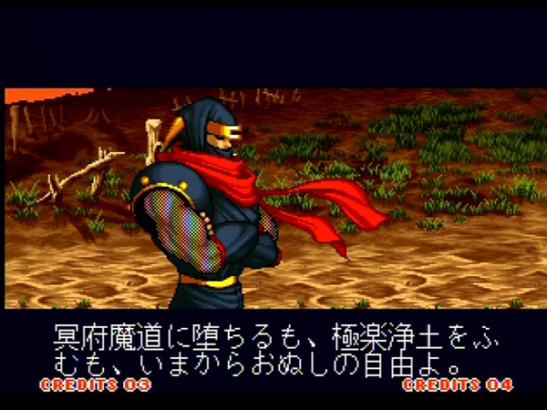
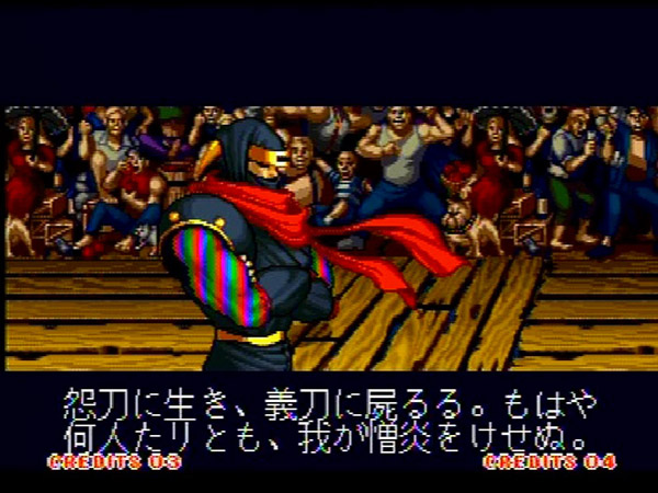
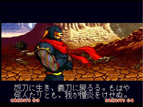
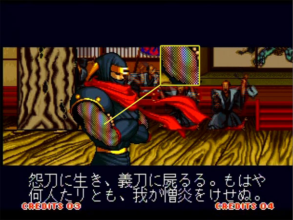
For those that are thinking of trying other values of capacitors, don't. It doesn't make a difference. There will still be noise in the signal which is very evident in the sleeves of Hanzo. The only thing that will get rid of the noise is Component video or RGB. Here are some other examples:
S-Video w/220uf Cap
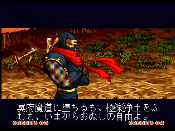
S-Video w/470uf Cap
S-Video w/470uf Cap with 0.1uf Coupling Cap
Mod your Genesis 1 to Use only 1 PSU with Sega CD
In this guide you will learn how to mod you Genesis 1 so you only need 1 PSU to pwer it while using a Sega CD Model 2. Since this is an advanced mod I will not post instructions on the basics like opening the console and the like.
Tools Needed:
Phillips Head Screwdriver
Wire Cutters
Soldering Iron
Solder
Hot Glue Gun
+9v PSU Capable of a minimum of 2 Amps (Negative Tip) - We have this in the store
18-24 gauge wire, I used 24 gauge for this mod
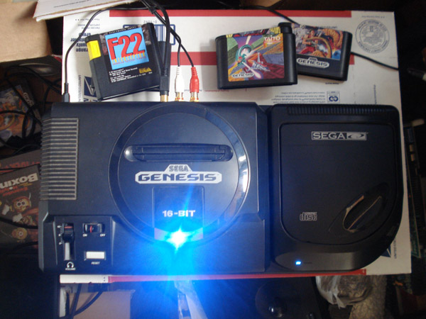
Picture of the Mod working with only 1 Power Supply hooked up. Ya those LEDs are bright when you look down at them.
1. Providing +9v to the Sega CD Model 2
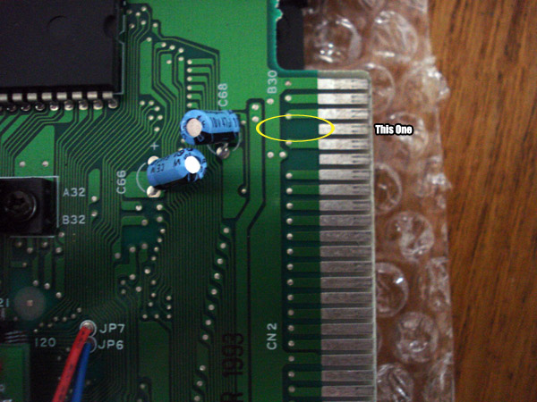
This part is pretty simple, just open your Genesis 1 console. We are looking at the PCB connector edge that connects to the Sega CD.
You will notice that a few pins are not being used at all. We will be using Pin #4.
Now apply some solder to the left side of the pin like below:
Route the wires around like so using hot glue to secure it.
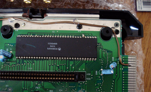
Now solder the other end of the wire to this point on the power jack of the genesis. This point is the source of the +9v going into the console.
That's all you need to do for this side of the console, go ahead and put it back together.
2. Setting up the Sega CD Model 2
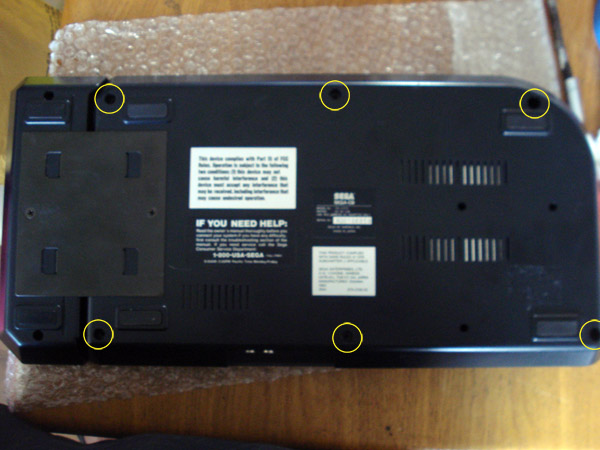
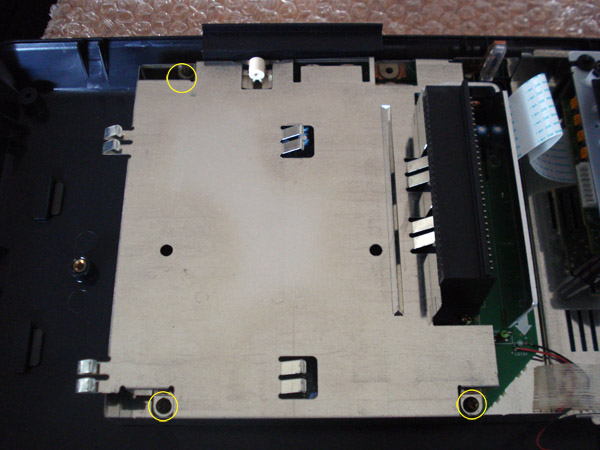
Now you will need to open your Model 2. There are 6 screws to remove to open:
Once open you will now need to remove 3 more screws to get to the board, then remove the 2 screws mounting the board next to the connector:
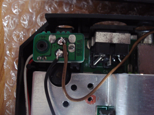
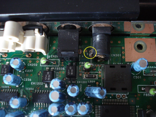
This is the point on the power jack that we will be soldering to:
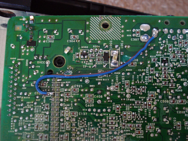
Go ahead and flip the board over and you will see this under the connector:
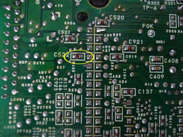
It's strange how the pin connects to nothing in the Genesis side but it has some extra filtering on the CD side. We will be removing the capacitor labeled C522. This capacitor is probably used for the Genesis 2 or something but who cares, we have Genesis 1 don't we?
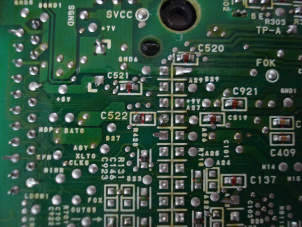
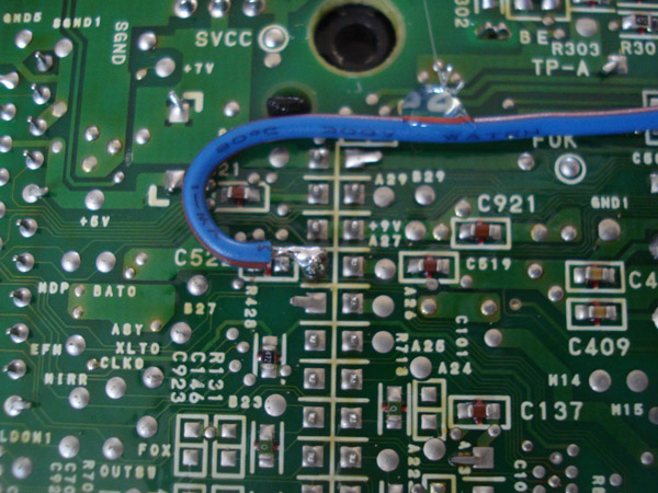
Once the capacitor is removed go ahead and connect a wire from Pin #4 to the point on the power jack.
I routed it this way since there is a spacer where the connector is mounted so it won't get smashed.
Well that's it, go ahead and put everything back together and play your Sega CD Model 2 with no additional power supplies. Remember that you need a power supply that puts out at LEAST 2 Amps, anything less will create some problems when playing the more graphically demanding games. You can always create a Y adapter for your PSU instead if you prefer to do it that way instead of modding your Genesis like this.
Xian Xi