Tutorials : CMVS MV1-FS
|
How to Consolize an MV1-FS Board |
|
|
| In This Guide |
|
In this guide I will show you how to consolize an MV-1FS MVS board. This guide can also be used on an MV-1F. |
| Parts Needed |
|
|
| Getting Stereo Sound |
|
The MV1-FS board does give Stereo Sound off the jamma edge via a switch as well as via the Headphone connector. We will be taking the stereo sound from the headphone connector. First, you need to locate the solder points. There are 3 points under the headphone connector we will be using. Take note that if when you complete your CMVS and the sound is too low you can adjust the volume slider on the front of the board to increase volume. I like to mark the ground wire on both ends of the wire with a black sharpie. I usually tap it so the 3 wires are Ground, Left, Right. This way when I wire them up I don't get confused.
|
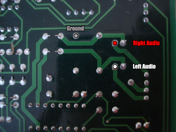 In Figure 1-1 is the Headphone connector area on the underside of the MV1FS. |
| The Video Encoder |
|
The Video Encoder uses these signals: Red, Green, Blue, Sync, Video Ground and +5v. These signals are pulled from the MVS board at these corresponding pins: Connect the above pins to the input on the video encoder. Take the wires from the output of the encoder and connect those to your Video jacks. Remember to connect the center pin on the jacks to the output of the video encoder. The video ground from the encoder connects to the outside of the jacks. |
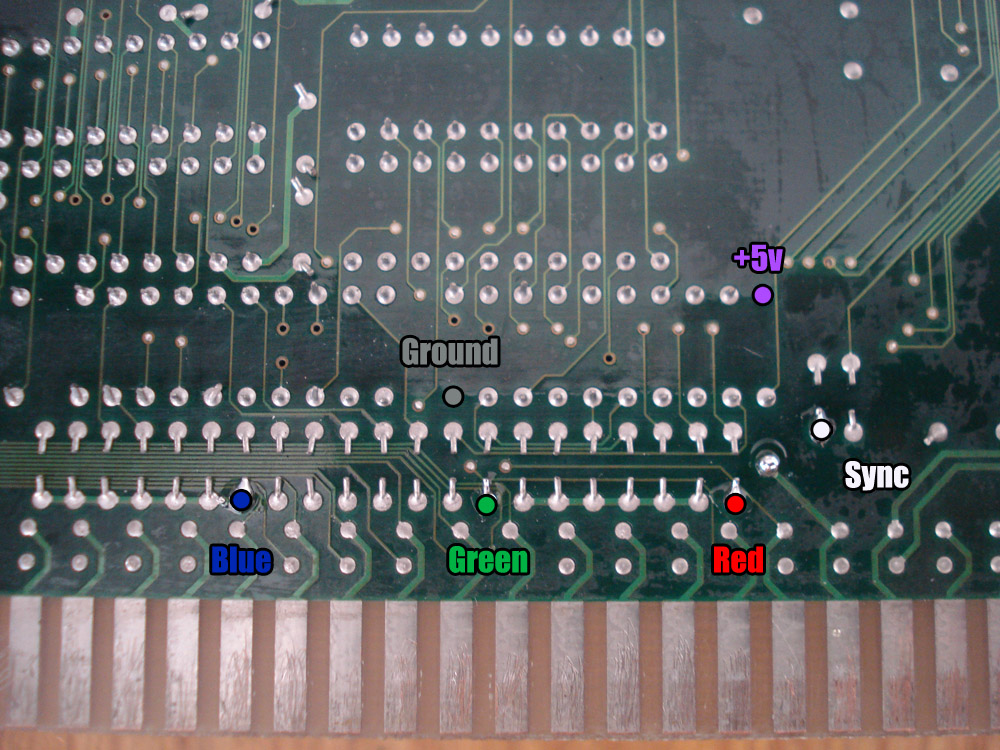 In Figure 1-1 is the RGB area on the underside of the MV1FS. The points indicated are the optimal points to tap the signals. |
| Passing the Wires |
|
Once you tap the RGB signals and audio you need to get them to the top board. You have 2 options, you can run the wires on the underside to the back of the board then through the B board to the cart holder or you can make a hole in the board and pass them through. You will need a Unibit to make the hole. |
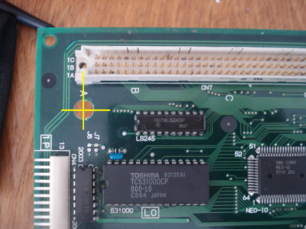 In Figure 1-1 is the top left corner on the MV1FS. You will need to drill a small pilot hole lined up in the area pictured. This is the optimal area since there are no traces under it. |
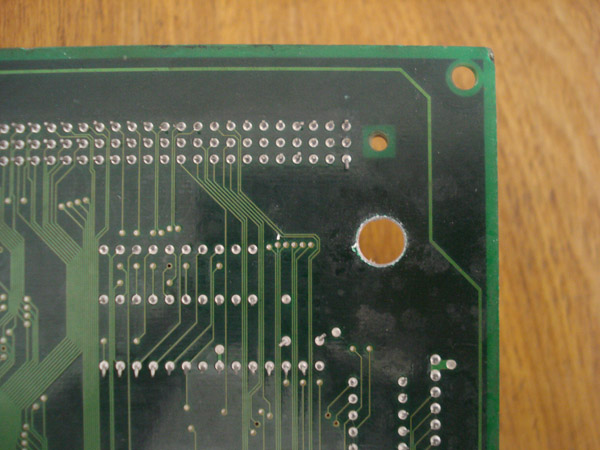 In Figure 2-1 is the top right corner on the underside of the MV1FS. Here you can see the other side of the hole you made. Use your judgement as to what size hole you need. Just remember to not cut the 3 traces to the left of the hole. |
| Mounting the Encoder |
|
Once you tap the RGB signals and run them through the hole all you need to do is mount the encoder. Drill 4 holes. The 4 holes you will be drilling will line up with the mounting holes of your encoder. Make sure you check the distance between the 2 pairs of dots before drilling. You will need a 1/8" drill bit to make the hole or your Unibit. |
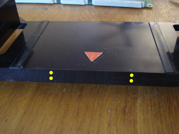 In Figure 1-1 is the backside of the cart guide from the MV1FS note the location of the red triangle. Once you drill the 4 holes simply use the zip ties to mount the encoder to the plastic cart guide. |
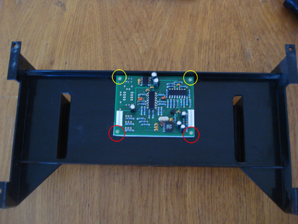 In Figure 2-1 is the underside of the cart guide on MV1FS. Here you can see the other side of the cart guide and what's actually happening. The area with yellow circles indicates where the zip ties will be, the red areas are where you will be applying hot glue to secure the other side of the encoder. You do not need to use excessive amounts of hot glue but if you want to reduce the chance of the glue losing grip from the cart guide use at least a half stick and the best way is to run it along the sides of the encoder and the front so 3 sides with glue. |
| Mounting the Jacks |
|
Now it's time to mount the jacks. Audio, Video, Power and the Power Switch You will need a Unibit to make the holes for your jacks. |
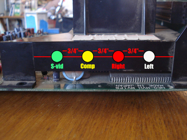 In Figure 1-1 is the right side of the cart guide from the MV1FS. I usually space my jacks with 3/4" space between. The easiest way to line up your jacks is to use 1" blue masking tape and make a line down the middle at the 1/2" mark so you have a centered line. From there you can plot out the layout of you jacks. Don't make them too close as some cables have thick housings and may hit each other. I find that 3/4" is the best distance. Please note that if you plan to have Component output then you will need to mount them on the back panel. |
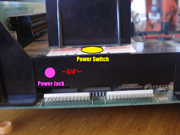 In Figure 2-1 is the left side of the cart guide on MV1FS. Here you will be mounting the power jack and the power switch. This is the layout I use. Of course you can mount the switch and jack elsewhere. |
| Powering the Board |
|
Powering the board is simple, you just provide +5v and ground. With the PSU I recommended all you need is a panel mount 2.1/2.5mm barrel jack which can also be purchased a Jameco. The barrel jack has 3 pins but you will only be using 2 of them. Remember that the PSU has positive tip polarity which means that the center pin will carry the +5v supply, the edge will be the ground. I always use a multimeter as a habit when doing it just to ensure everything is correct. Just mount the barrel jack and plug in the psu without wiring it to the board and use your tester to check which pin is which. Once you mounted the power jack and switch you will need to send the power to the board. Remember that the ground from the power jack goes straight to the indicated capacitor. The +5v goes from the power jack to the power switch then to the +5v spot on the indicated capacitor. |
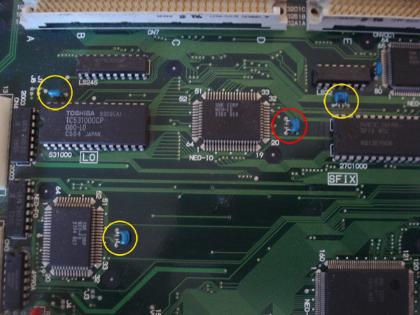 In Figure 1-1 are the capacitors you can send the power to. The red one is the one I use pesonally since the orientation and location is best. |
 In Figure 2-1 are the points to solder to. |