Tutorials : CMVS
|
How to Consolize an MVS Board |
|
|
| In This Guide |
|
In this guide I will show you how to consolize an MV-1C MVS board. What is consolization you ask? Consolization is basically turning an arcade board which is made to be played in an arcade cab playable on a regular TV with control pads just like any other home console, hence the term "Consolization". The difference between a CMVS and a supergun is that a CMVS is a "dedicated" supergun that only plays MVS games. This is where you ask yourself "Do I want to make a CMVS or a supergun?". You decide. |
| Parts Needed |
|
|
| Enclosures |
|
For enclosures it is all up to you, you can either do an "Open Face" CMVS which is a bare board with no fancy enclosure or a fully cased CMVS. Keep in mind that putting an MVS board into a case can be difficult and also may take you a while to find an enclosure you like. Several companies make plastic, wood and metal enclosures. Hammond Manufacturing makes both plastic and metal ones. Other companies like PacTec only make plastic ones. Some CMVS builder have used Plexiglass, old PC cases and even NGH and NeoCD cases. Making an "Open Face" CMVS takes about 3-5 days to complete depending on cleanliness. An enclosed CMVS can take up to 3 weeks depending on difficulty with the casing material. However an "Open Face" 2 slot will only take you about 8 hours or less total build time, this is due to having everything you need already on the board and all you need is a PSU and RGB > NTSC Encoder. |
| Stereo Sound |
|
The MV-1C board does not give Stereo Sound off the jamma edge so you will need to tap the sound directly from the chip to achieve Stereo Sound.
First, you need to remove the heat sink on the board. That is the big silver thing on the bottom right corner of the board. You can remove it by either desoldering it or just clipping the legs. I don't ever plan on re-using them so I just cut the legs and then desolder the 2 posts holding it to the board. Click on the images for a larger view |
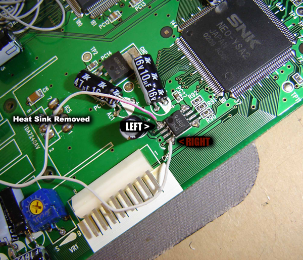 In Figure 1-1 is the onboard sound chip on the MV-1C.
|
 Here you can see that you can remove the following as they are no longer needed. You do not need to remove these to get stereo sound:
|
| Powering the Board |
|
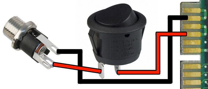
Powering the board is simple, you just provide +5v and ground. With the PSU I recommended all you need is a panel mount 2.1mm barrel jack which can also be purchased a Jameco. The barrel jack has 3 pins but you will only be using 2 of them. Remember that the PSU has positive tip polarity which means that the center pin will carry the +5v supply, the edge will be the ground. I always use a multimeter as a habit when doing it just to ensure everything is correct. Just mount the barrel jack and plug in the psu without wiring it to the board and use your tester to check which pin is which. Just remember that when powering your board with only +5v the sound will not come off the jamma edge as that is where the amplified sound is tapped to. You will need to find the source before it hits the amplifier, for an MV-1C this mod is shown below. Once you confirm which pin is the +5v go ahead and connect it to a power switch, you can use a rocker switch for this or whatever you choose. From there connect the power to Jamma PINs 3,4,C,D. And the ground to Jamma PINs 1,2,A,B. When adding a power switch, you will need 2 wires going to the switch. The switch needs to act as an interupt so when you flip the switch on and off it stops and starts the flow of the +5v to the board. See pic below.
|
| The Video Encoder |
|
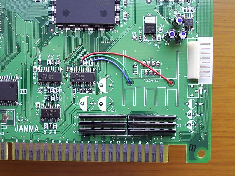
The Video Encoder uses these signals: Red, Green, Blue, Sync, Video Ground and +5v. These signals are pulled from the MVS board at these corresponding pins: Connect the above pins to the input on the video encoder. Take the wires from the output of the encoder and connect those to your Video jacks. Remember to connect the center pin on the jacks to the output of the video encoder. The video ground from the encoder connects to the outside of the jacks. RGB Output for the Purists If you don't plan on using encoders and just want RGB goodness, you should at least use an RGB buffer like a THS7314/16 or a THS7374. You can get PCBs for DIY assembly on OshPark or even find pre-assembled versions on ebay and all over the net. You would use the same RGB and Sync tap points as if using an encoder like shown above.
|
| Adding Controller Ports |
|
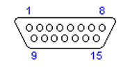
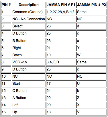
Above is a picture of a DB15 controller port viewed from the front side, the solder side will be opposite. Now for these projects you do not "have to" use these ports since you are making it your own. But if you would like to use your existing Neo Geo controllers you should use them unless you will also build a small converter that has a DB15 connector to convert to your custom pinout if you choose. Even though there are 2 pins that are used for the D button, only Pin 4 is used for 99% of the games. Pin 9 is used basically for the rare mahjong controller. Keep in mind that if you do not plan on using a Unibios you must wire up the coin buttons (Pin 16, T)to the select buttons (Pin 3) on the Neo controller. If you use a Unibios it makes the select button act as a coin button. If you do not want to wire it up to the controller you can add buttons on your CMVS for coins, I personally think that's retarded. The standard Neo Geo Controller pinout:
|
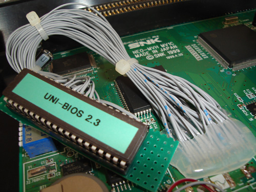
| Adding a Unibios |
|
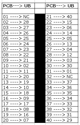
A Unibios is an essential tool for your CMVS. One of the great things about it is that it lets you turn your CMVS into an AES with the console mode option. On an MV1C the Bios is a surface mount chip like the MV-1B, unlike the other boards with a socketed bios you will need to wire up a socket to add a Unibios. First thing you should know is that both chips have 40 pins BUT are not pin for pin as far as output. You will need to follow the pinout from the Unibios chip to the MV-1C bios. The MV-1B has a pin for pin connection(1-1, 2-2, 3-3, etc.) unlike the MV-1C as seen below. For this you will need: Mount the socket to the Perfboard and solder it. From here you can either solder the 40 wires to the socket first or to the board. Some people use ribbon cable which is easier to use. Follow the pinout below to solder the pins correctly.
Here is another image of the Unibios with corresponding pins from the PCB.
*If After you connect the Unibios and it doesn't boot, you may need to bridge pins 38, 39 and 40. I've only had to do this on 1 board. *The MV1C can run off any MVS bios so you can do the socket mod and use another bios if you plan to get a Unibios later but want to do the mod now. Here is a picture of a completed Unibios Socket on an MV1C:
**There is a new product called the NeoBiosMasta which elminates the need to do this mod. Cost is about $13 and saves a lot of time. I recommend it but if you are using an enclosure that only has so much clearance, wiring it like above may be the best bet for you. Please purchase the NeoBiosMasta or the Virtual Memory Card (VMC) from Neogeo Fan Club as he is the original creator and there are others profitting off of his hard work. |
| RGB Output Socket(AES) Style |
|
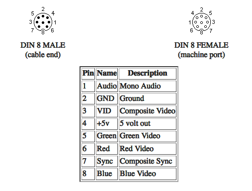
For the RGB socket it is very simple. Just follow the pinout of the socket and tap the signals from where you were instructed to earlier in the DIY. The pinout labeled "Cable End" is the pinout which is what you would see on the solder side of the socket. The Pinout is:
**Image Courtesy of Gamesx.com |
| Extras?? |
|
Guide by Xian Xi |